parts:
1) cheap 1 channel r/c car ($15 at KB Toys)
2) 5v relay (<a href="http://www.digikey.com/scripts/DkSearch ... >something like this should work</a>)
3) sprinkler valve (with solenoid)
4)a standard diode (<a href="http://www.digikey.com/scripts/DkSearch ... 180EGOS-ND"> this will work</a>)
5)two 9v battery clip (go to radio shack or take them from broken stuff)
6)assorted batterys
7)antenna wire (i used 20ft of enamel coated 26 gauge because it was green and blended well)
8)assorted bits of wire
tools:
dremel
wire cutters
multi meter (this is absolutely essential)
soldering iron
....part one : disassembly....
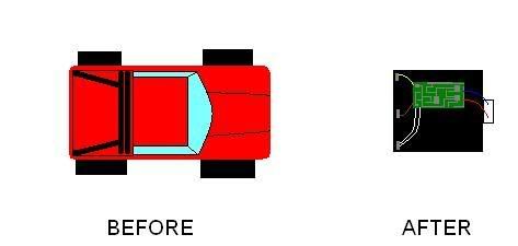
take off the r/c car body, then use the dremel to cut the forward section of the car off. next remove the motor from its housing and unsolder the two wires going to it, now cut off the rear section of the car using the dremel. all that should remain of the car is the battery compartment, a small switch, and the circuit attached to the battery box. i have provided a diagram with the before and after of this step
<img src="http://i78.photobucket.com/albums/j85/i ... nator1.jpg">
...part two : re-wiring....
*note: i have written this part assuming you have acquired the same or very similar model r/c car as i used*
if you are using the same model car as i am then you will notice as soon as you turn on the car it should start moving backwards in circles, if we do not fix this as soon as we turn on the "detonator" the device will fire becuase any voltage forward or reverse can activate the relay. this is why we need the diode (diodes only allow current to flow in one direction) but before we solder the diode we are going to need to know which of the motor leads to solder it to. this is very simple to determine... turn on the r/c car do not touch the remote and use the multi meter to measure the voltage coming out of the wires which used to connect to the motor. if there is a minus sign on the screen switch the multi meter leads until it disappears then solder the diode (backwards) to the positive lead then turn the car off (when the multi meter is reading a positive voltage it would be the wire the red lead is touching) while you were reading the voltage of the motor you should have noticed something it was only 3v this will not activate our 5v relay (for obvious reasons) this is also very easy to fix. if you look at the battery box you should see there are three sets of wires connected to it (instead of the usual two)what you need to do here is find the positive 3v wire and connect it to the positive 5v lead on the box (again you need to use the multimeter but you do not need the car to be on) after this is done there should only be two sets of wires connected to the battery box.
...part three : wiring....
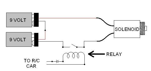
most of the hard stuff (if you would even consider it that) is done now all we need to do is connect the relay and 9v batterys. first solder the wires that used to connect to the motor to the coil side of the relay. next solder the 9v battery leads in series then connect one of the wires to the switch side of the relay and the other to the solenoid. lastly connect the remaining solenoid wire to the remaining switch lead on the relay.and thats pretty much it just connect up an antenna and your done. heres a basic diagram of what you should have when your done
<img src="http://i78.photobucket.com/albums/j85/i ... ircuit.jpg">
...the remote...
the remote in its stock form will work just fine the only reason i put mine in a cell phone was to give it that "terrorist effect" it was designed to be used in airsoft games and i am known for using AKs (considered a "terrorist weapon" by most) so i thought it fit nicely. to get it to fit in the phone i shaved off part of the circuit using a dremel then wired the forward button to the end button on the cell phone key pad. lastly i modified it to run off a car key fob battery (which is significantly smaller than a standard 9 volt)
...other info....
this is a very basic r/c circuit it is prone to picking up interference this was designed to be used in the woods acting as a remote detonated mine. you must remember that this cannot be used in a modded sprinkler valve unless you bough a separate solenoid valve to pilot the sprinkler valve (like a small 1/4 npt solenoid valve or something). if the device goes off as soon as you turn on the power switch that means the diode was inserted the wrong way this is simple to fix just unsolder it turn it 180 degrees and solder it back in. this is a relatively weak r/c receiver, in my mine it is paired with about 20ft of antenna which would normally be wrapped around a nearby tree giving it an effective range of over 100ft. if you plan on using this underground (in the case of my mine) encase all the electronics in hot glue so they are not damaged by water. one last thing is if the device seems to detonate randomly if its not interference its the antenna... make sure the wire coming in contact with the circuit boards antenna lead doesn't make a metal to metal contact just keep the insulation on it
if anything doesn't seem clear just ask
remote activated sprinkler valve
-
singularity

- Corporal 5

- Posts: 982
- Joined: Mon Jun 26, 2006 10:53 pm
- Location: someplace
- Contact:
Last edited by singularity on Fri Aug 31, 2007 7:47 pm, edited 2 times in total.
be sure to check out my <a href="http://www.spudfiles.com/forums/ak-styl ... 9.html">AK Styled Vortex Gun</a> and my <a href="http://www.spudfiles.com/forums/at-4-t9627.html">AT-4 Rocket</a>
upcoming projects... finalized clip fed BBMG and ball point pen sniper
upcoming projects... finalized clip fed BBMG and ball point pen sniper
-
jimmy101

- Sergeant Major 2


- Posts: 3210
- Joined: Wed Mar 28, 2007 9:48 am
- Location: Greenwood, Indiana
- Has thanked: 7 times
- Been thanked: 18 times
- Contact:
Nice write-up.
Maybe add to the Spud Wiki?
There are a couple things that can substitute for the cheapo RC car ...
Cordless telephones usually have a remote pager or "locate" button. SixMhz has a nice write-up on how to convert one to a wireless firing system. (http://www.angelfire.com/80s/sixmhz/rcphone.html)
You can sometimes find complete RC systems for very cheap. For example, All Electronics has a "keyless entry" system with two fobs (like a car uses) and the receiver. It'll easily handle the current required for a solenoid.
http://www.allelectronics.com/cgi-bin/i ... _AMP_.html for $18.75. A little pricier than a cheapo RC but you wouldn't need a relay since this'll handle 6A and 12V.
Or, for $35, you could get a wireless "REMOTE CONTROL CAMERA SCANNER". Probably use it to point and fire the gun.
http://www.allelectronics.com/cgi-bin/i ... NNER_.html

-
singularity
- Corporal 5
- Posts: 982
- Joined: Mon Jun 26, 2006 10:53 pm
- Location: someplace
- Contact:
o man that $35 one is crazy can you imagine what type of damage a mini vortex gun (which i just happened to finish) could do on that. but yea the idea behind this was it cost virtually nothing for me because everything was lying around or salvaged from old pc boards. those key fobs look like they are inferred meaning it would be line of sight type thing.
ps - how would i ad this to the wiki?
ps - how would i ad this to the wiki?
be sure to check out my <a href="http://www.spudfiles.com/forums/ak-styl ... 9.html">AK Styled Vortex Gun</a> and my <a href="http://www.spudfiles.com/forums/at-4-t9627.html">AT-4 Rocket</a>
upcoming projects... finalized clip fed BBMG and ball point pen sniper
upcoming projects... finalized clip fed BBMG and ball point pen sniper

-
singularity
- Corporal 5
- Posts: 982
- Joined: Mon Jun 26, 2006 10:53 pm
- Location: someplace
- Contact:
well my particular choice in r/c car does not have servos and i don't feel like spending a bunch of money on a nice r/c system
be sure to check out my <a href="http://www.spudfiles.com/forums/ak-styl ... 9.html">AK Styled Vortex Gun</a> and my <a href="http://www.spudfiles.com/forums/at-4-t9627.html">AT-4 Rocket</a>
upcoming projects... finalized clip fed BBMG and ball point pen sniper
upcoming projects... finalized clip fed BBMG and ball point pen sniper
-
SpudBlaster15
- First Sergeant 3


- Posts: 2400
- Joined: Wed Oct 18, 2006 11:12 pm
- Has thanked: 2 times
- Been thanked: 10 times
Lorem ipsum dolor sit amet, consectetur adipiscing elit. Cras nec placerat erat. Vivamus dapibus egestas nunc, at eleifend neque. Suspendisse potenti. Sed dictum lacus eu nisl pretium vehicula. Ut faucibus hendrerit nisi. Integer ultricies orci eu ultrices malesuada. Fusce id mauris risus. Suspendisse finibus ligula et nisl rutrum efficitur. Vestibulum posuere erat pellentesque ornare venenatis. Integer commodo fermentum tortor in pharetra. Proin scelerisque consectetur posuere. Vestibulum molestie augue ac nibh feugiat scelerisque. Sed aliquet a nunc in mattis.
Last edited by SpudBlaster15 on Wed Jul 14, 2021 5:32 pm, edited 1 time in total.
-
thespeedycicada

- Specialist 4

- Posts: 429
- Joined: Sun Aug 12, 2007 1:28 am
you can buy servos for 20 bucks at hobby stores just figure out how to wire them up possibly the system you described?
-
TwitchTheAussie

- Corporal 5
- Posts: 980
- Joined: Tue Feb 06, 2007 3:23 am
Finally Singularity, finally Nice thanks man. Time to get to work.
Raise your horns if you love metal.
CpTn_lAw
-spudgunning is like sex, once you've tasted, you can't wait til next time.
CpTn_lAw
-
singularity
- Corporal 5
- Posts: 982
- Joined: Mon Jun 26, 2006 10:53 pm
- Location: someplace
- Contact:
SpudBlaster15 - yea this particular car starts moving backward as soon as its turned on thats why i needed the diode so only the forward signal from the remote would activate the coil (its the crappiest r/c car on the market)
thespeedycicada - yea i could do it but it would involve micro controllers and i think the cheap $35 one would be far less expensive/time consuming
TwitchTheAussie - your welcome sorry it took so long
thespeedycicada - yea i could do it but it would involve micro controllers and i think the cheap $35 one would be far less expensive/time consuming
TwitchTheAussie - your welcome sorry it took so long
be sure to check out my <a href="http://www.spudfiles.com/forums/ak-styl ... 9.html">AK Styled Vortex Gun</a> and my <a href="http://www.spudfiles.com/forums/at-4-t9627.html">AT-4 Rocket</a>
upcoming projects... finalized clip fed BBMG and ball point pen sniper
upcoming projects... finalized clip fed BBMG and ball point pen sniper
-
jimmy101
- Sergeant Major 2
- Posts: 3210
- Joined: Wed Mar 28, 2007 9:48 am
- Location: Greenwood, Indiana
- Has thanked: 7 times
- Been thanked: 18 times
- Contact:
Nope, both are radio devices, not infrared. The fobs really are the same as the remote unlock fobs of most newer cars.singularity wrote:... those key fobs look like they are inferred meaning it would be line of sight type thing.
ps - how would i ad this to the Wiki?
Your first additions to a Wiki usually are kind of a PITA since Wiki has it's own way of doing things.
Go to the spud Wiki http://www.spudfiles.com/spud_wiki/inde ... =Main_Page
Try to login using your Spudfiles ID, if you can't you should register.
Try searching for "remote" to see if there are any pages already. Or, start at the "ignition page" http://www.spudfiles.com/spud_wiki/inde ... ion_source
Click the edit tab and add an entry for remote ignition.
When you save the page you can then click on the new link you created and wiki should come back saying the pages doesn't exist and would you like to create it? Say yes, then go and copy your post from the forum into the wiki edit page. It'll then probably take some fiddling to get everything working right but it isn't too difficult (or obscure).
-
TwitchTheAussie
- Corporal 5
- Posts: 980
- Joined: Tue Feb 06, 2007 3:23 am
Its ok man. Ive just picked a design I liked and Im dieing to get started and now I can thanks man 
Raise your horns if you love metal.
CpTn_lAw
-spudgunning is like sex, once you've tasted, you can't wait til next time.
CpTn_lAw

Hi,
I like the idea, but:
- I think the cheapo RC cannot be considered safe against accidental firing because of interference from mobile phones etc. Maybe a warning that it could potentially fire at any time when on would be good? Or maybe everybody understands that.
- The back EMF from the relay (100s of volts) when cutting off power to it could destroy the diode, maybe making it conductive in both directions. A 100 nF or so capacitor in parallel with the relay coil will prevent that.
Regards
Soren
-
iknowmy3tables
- Staff Sergeant

- Posts: 1596
- Joined: Fri Dec 15, 2006 3:57 pm
- Location: maryland
- Has thanked: 3 times
- Been thanked: 9 times
thanks man now I know how to do some remote switches
hey how well do you think the pocket rc cars work
hey how well do you think the pocket rc cars work
-
jimmy101
- Sergeant Major 2
- Posts: 3210
- Joined: Wed Mar 28, 2007 9:48 am
- Location: Greenwood, Indiana
- Has thanked: 7 times
- Been thanked: 18 times
- Contact:
I was wondering about that as well. The usual solution is to put a diode in parralel across the coil to kill the back EMF you get when the coil is switched off. I don't think putting a cap there will do anything except make the relay work slower.dongfang wrote:Hi,
I like the idea, but:
- The back EMF from the relay (100s of volts) when cutting off power to it could destroy the diode, maybe making it conductive in both directions. A 100 nF or so capacitor in parallel with the relay coil will prevent that.
Regards
Soren
If it was me aI would just move the diode shown like this;
- Attachments
-
- rcdetonatorcircuit_mod.gif (18.33 KiB) Viewed 7839 times
-
jimmy101
- Sergeant Major 2
- Posts: 3210
- Joined: Wed Mar 28, 2007 9:48 am
- Location: Greenwood, Indiana
- Has thanked: 7 times
- Been thanked: 18 times
- Contact:
I was wondering about that as well. The usual solution is to put a diode in parallel across the coil to kill the back EMF you get when the coil is switched off. I don't think putting a cap there will do anything except make the relay work slower.dongfang wrote:Hi,
I like the idea, but:
- The back EMF from the relay (100s of volts) when cutting off power to it could destroy the diode, maybe making it conductive in both directions. A 100 nF or so capacitor in parallel with the relay coil will prevent that.
Regards
Soren
If it was me, I would just move the diode as shown in the picture below.
Whether of not you need the diode depends on what the "R/C car" circuit is like. A simle battery plus switch wouldn't need the diode protection. Pretty much anything more complex than a battery+switch probably does need the diode protection. (Just 6V on the wrong pins of a generic transitor will fry it.)
- Attachments
-
- rcdetonatorcircuit_mod.gif (18.33 KiB) Viewed 7839 times
Create an account or sign in to join the discussion
You need to be a member in order to post a reply
Create an account
Not a member? register to join our community
Members can start their own topics & subscribe to topics
It’s free and only takes a minute
Sign in
-
- Similar Topics
- Replies
- Views
- Last post
-
- 10 Replies
- 5390 Views
-
Last post by jackssmirkingrevenge
-
- 1 Replies
- 4752 Views
-
Last post by jackssmirkingrevenge
-
- 9 Replies
- 5147 Views
-
Last post by TurboSuper
-
- 3 Replies
- 1654 Views
-
Last post by roboman
-
- 4 Replies
- 3122 Views
-
Last post by Pilgrimman


