Page 1 of 2
full auto bolt-valve combo design
Posted: Sat Apr 05, 2008 5:05 pm
by iknowmy3tables
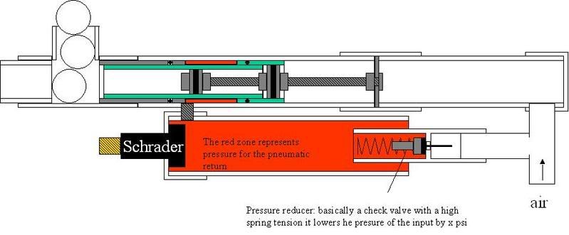
I'll have to think of a good acronym for this, I went back to auto pistons, and piston valve bolt combo designs, and I thought of this as a fully automatic valve and bolt system , with a constant air source this should run full auto on it's own, I don't have the proper spring for the bolt return so I designed a pneumatic spring system that has just a little less pressure than the input
so basically there are several seals here made using the whole brian washer and sheet rubber sandwich thing the diagram should explain it all
 Special Thanks to Flash
 when trying to think of ways to fix his design I came up with this
I'm currently working on the prototype
Posted: Sat Apr 05, 2008 5:18 pm
by Skywalker
Looks good, looks good!
Posted: Sat Apr 05, 2008 5:27 pm
by Antonio
Damn, you made some nice drawings there. You should make an animation from it. The thing I dont get is how the actuate the valve. Is the back of the piston stem connected to the back? Or is it not supposed to move. I think this design looks like the autobreech system, but it has a special air spring'' feature. Which is nicely thought of:) It comes from all branches. But yeah I am curious about ur acuation.
Posted: Sat Apr 05, 2008 5:33 pm
by judgment_arms
Looks a tad overly complex until you really start looking at it, then you realize it’s ingenuously simple.
Only thing is, is there enough surface area on the back of the bolt to over come the return system?
Lookin’ good though.
Posted: Sat Apr 05, 2008 5:35 pm
by Skywalker
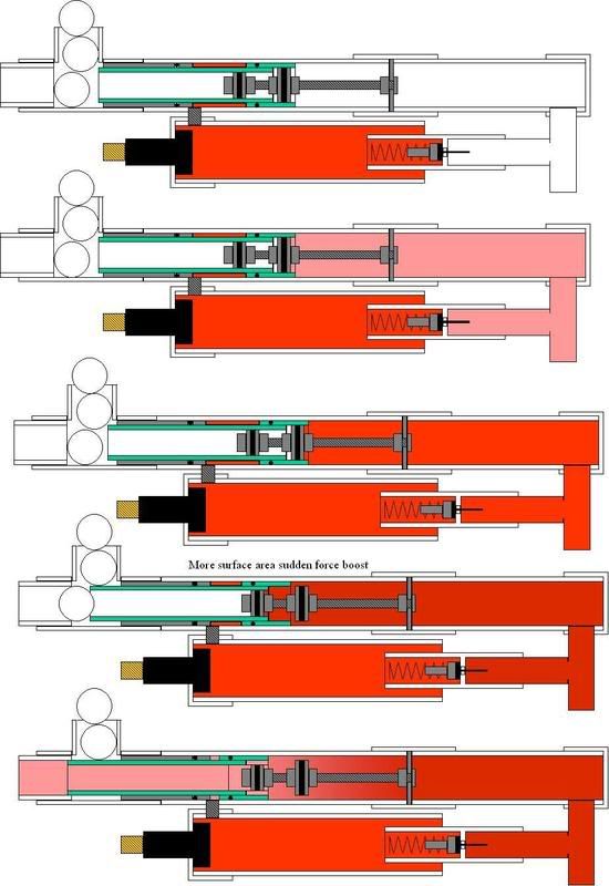
Looks to me like the rod with the pistons on it is anchored at the rear so it doesn't move, it just kinds plugs the center of the bolt untill the bolt moves forward. The triggering should in theory happen just by supplying air to the manifold: as the manifold pressure increases, the force overcomes the pneumatic spring and pushes the bolt forward. This exposes slightly more of the bolt to the force of air (note that the forward piston/seal is smaller), and then the bolt shoots forward, closes off the ammo tube, and fires. Then the pressure in the manifold drops so that the bolt returns.
Posted: Sat Apr 05, 2008 5:56 pm
by iknowmy3tables
for actuation , I'm thinking of a simple on-off valve input
sky walker's got it, before the bolt moves forward there is equal surface area on both side of the bolt which is why the return side must have that reduced pressure, once the air supply can break equilibrium the bolt moves forward and suddenly there is even more surface area thus more force and it accelerates blasting open like a piston valve, bwahhahahah

Posted: Sat Apr 05, 2008 6:13 pm
by Skywalker
Come to think of it, that's pretty much just a fancy-butt blowforward breach. I'd say relative to the diagram, the difference in surface area probably needs to be greater at that step. That way, the valve will blow open violently enough to vent the pressure down to where it will actually close. Hmm, you'll probably want a firing chamber hooked up to that manifold, so you can afford to moderate the flow a bit lower (to allow the thing to shut) without loosing power. Or perhaps there might be a way to link that bolt to a mechanism to valve that could shut off the flow into the manifold when the bolt goes all the way forward.
Yeah, looks like you've licked the blowforward valve problem though!
Posted: Sun Apr 06, 2008 2:37 pm
by iknowmy3tables
their isn't much more I can do for the surface area diffrence, I could wrap the bolt in 1/2"pvc but I'll have to look into the types of pipe combinations along with things compatible o-rings in my o-ring kit, I don't have a lathe, just a belt sander to grind down pipe no persion carved oring grooves just pipe sleeves it'll probably look like this
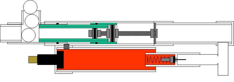 tell me if you have a problem with the larger bmp, because saving as jpegs have worse quality for simple diagrams like this
what do you mean by a firing chamber, do you mean like a larger chamber volume?
Posted: Sun Apr 06, 2008 3:03 pm
by psycix
tell me if you have a problem with the larger bmp, because saving as jpegs have worse quality for simple diagrams like this
jpg = quality loss
bmp = huge file size
use PNG
Low file size, no quality loss
Posted: Sun Apr 06, 2008 4:15 pm
by socoj2
heh its an unbalanced spool valave..
Ala` Ion
Posted: Sun Apr 06, 2008 4:17 pm
by Antonio
I still dont get what the bottom poppet/schrader valve is for? You said you had a on/off air supply. But how does this schrader play a role?
Posted: Sun Apr 06, 2008 11:43 pm
by jackssmirkingrevenge
Ah, I get it now

Very interesting concept, it certainly merits further thought. The tricky part I can see is getting the bolt to start moving as opposting to "hanging" as seems to be the problem with most of the auto designs that have cropped up here.
edit: shitty animation I know but I was in a hurry, I'll make a better one later.
Posted: Mon Apr 07, 2008 5:42 am
by Antonio
Ah k so the reservoir with the two schrader valves is only for the airspring? > If so> it could be lots smaller I guess.
Posted: Mon Apr 07, 2008 10:38 am
by socoj2
This is a bolt design from a paintball Gun. Nothing revolutionary...
Posted: Mon Apr 07, 2008 10:41 am
by judgment_arms
socoj2 wrote:This is a bolt design from a paintball Gun. Nothing revolutionary...
Ah… I knew it looked familiar.
Well, I guess that means, if built right, it’ll work.