How Cool Would it Be?

Show us your pneumatic spud gun! Discuss pneumatic (compressed gas) powered potato guns and related accessories. Valve types, actuation, pipe, materials, fittings, compressors, safety, gas choices, and more.

Would you have any interest in an OTC, lathe-less, semi-automatic 2" gun?

Poll ended at Mon Aug 11, 2008 11:49 pm

Yes
10
100%
No need for another semi-auto design.
0
No votes
 
Total votes: 10
User avatar
mobile chernobyl
Corporal 3
Corporal 3
United States of America
Posts: 756
Joined: Sun Dec 03, 2006 11:53 am
Been thanked: 7 times

Sun Jul 27, 2008 11:49 pm

How cool would it be to have a semi-automatic, clip fed, caulk tube (or any other 2" barrel ammo) shooter?

Design summary:
-Ammo - 2" Dia 9" long Caulk tubes (any 2" ammo can be used)
-Air "Chamber" Volume per shot - 3-400 cu in (Can be more, easily, but ROF will suffer due to recharge rate)
-ROF - for 400 cu in "chamber" volume, 6 shots per minute, MAYBE 8, but recharge rate must be determined.
-Size - HUGE, think Anti Aircraft, like 30mm
-This design is not focused on high rate of fire like that of a machine gun, its rather based on a large bore, heavy projectile, magazine fed, semi-auto.

I have a design I'm working on, sofar its 100% OTC (no lathing required), and its on paper. I'm thinking of drawing it up solidworks if theres any interest. I'm kinda split decision on it. NO ONES made anything like it in spud gunning that i've ever seen. It uses an inline spool valve, Open bolt design. I'm just thinking of shooting caulk tubes cause their cool, and stuff, but anything 2" can be used. It will require orings... about 7 or 8 of them. They will all be external o-rings (::EDIT:: OK, one will be internal on a 2"X1.25" Reducer Bushing right at the barrel. I can explain how to make a jig with a dremel to make the internal o-ring groove if theres interest in the overall design) . It will require lube, prolly a good portion of it to cope with the irregularities of the PVC walls.

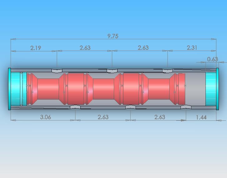
I've been interested in spool valves ever since I helped someone at Dye paintball work on a design for a prototype gun, and stumbled across the balanced beauty, and simplicity of spool valves. When I started at my last college, in the first year I designed this valve for our Engineering design competition. When everyone else took the easy route of just using 3 1/4" solenoids to drain 3 resevoirs of water at once, I took it upon myself to prove my knowledge of more advanced technology. So the "3port" valve was designed. I was told by the EE Professor I would not be able to get it to work, well he shut his mouth pretty quickly after he saw our working demo hehehe. The valve housing is 1.5" PVC (spud gunner represent YO) btw, the inside spool was 1.5" UHMW that I lathed down to the exact dimensions shown below. It was my first time physically making a spool valve I designed, and it worked!
Image

I'm really trying to transfer some of my paintball pnuematic design knowledge to spudguns to help advance the hobby for all of its participants. This design will require some time on my part to draft, and Will require even more troubleshooting it till its "recipe" ready. I'm just wondering how much of an interest there is for such a thing. It'll will be big in size, think anti aircraft. It's rate of fire will likely be design limited (not physically limited) to 6 shots per minute at the scale I am imagining (2" barrel, 3-400 cu in tank, shooting caulk tubes) . The valve body will be incased in 4" pvc, it can be any length really, the longer, the more volume in the spool valve, and vice versa.

I'm asking because theres already quite a few well thought out designs out there. Is there a demand for another one? One that could shoot a clip of CAULK TUBES?? You decide. :)

One last word - All the guns I've made up to this design would seem very low-tech (and I personally think they are) in comparison to this. It may be too complicated of a design for staying 100% OTC and sticking with PVC, but the desire is there on my part.[/b]
Last edited by mobile chernobyl on Mon Jul 28, 2008 1:43 am, edited 3 times in total.
User avatar
benstern
Corporal 5
Corporal 5
Posts: 908
Joined: Wed Sep 21, 2005 8:24 pm

Donating Members

Mon Jul 28, 2008 12:07 am

You can't use clips for caulk tubes. Only magazines would work for them.

clips are not magazines.
User avatar
mobile chernobyl
Corporal 3
Corporal 3
United States of America
Posts: 756
Joined: Sun Dec 03, 2006 11:53 am
Been thanked: 7 times

Mon Jul 28, 2008 12:11 am

Sorry, I am not well versed in the differences between the two benstern. I had, before you spoke up, considered them one and the same. Could you please explain the differences.

Thanks :)
User avatar
benstern
Corporal 5
Corporal 5
Posts: 908
Joined: Wed Sep 21, 2005 8:24 pm

Donating Members

Mon Jul 28, 2008 12:17 am

this should clear it up.
Image[/img]
User avatar
mobile chernobyl
Corporal 3
Corporal 3
United States of America
Posts: 756
Joined: Sun Dec 03, 2006 11:53 am
Been thanked: 7 times

Mon Jul 28, 2008 12:21 am

http://myspacetv.com/index.cfm?fuseacti ... id=7609197

Haha heres a short video I was looking at got it while you were posting. Same explanation.

I think 95% of people make the same mistake I did im my first post every day. I'm happy to be enlightened on this important matter :D
User avatar
mobile chernobyl
Corporal 3
Corporal 3
United States of America
Posts: 756
Joined: Sun Dec 03, 2006 11:53 am
Been thanked: 7 times

Mon Jul 28, 2008 1:18 am

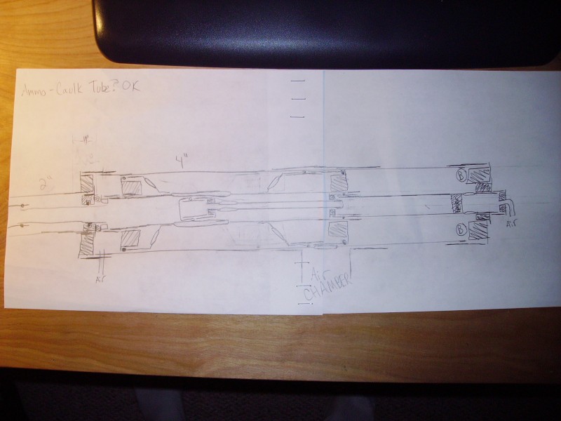
ARggggg, couldn't resist. Heres the rough sketch. I just finished tweaking it, and, althougth not everything is in scale, or to proper length, it looks like its gonna work!

-Lines represent tubing
-Fittings are obvious.
-Bushings are hashed diagonal lines
-Slots or holes are elongated ovals
-Orings are small circles or shaded dots
-Cirlces with B are bumpers
-The squigly line block in the middle tube towards the rear is a poured epoxy air blocking seal
-Air means air inlet for forward and reward movement of Spool
-Air CHAMBER means the air resevoir (larger than the spool resevior to aid in faster refilling and less shoot-down at sustained ROF's)
-The MAGAZINE (get it right or Gunny will beat yo a$$ nucka) is not drawn, but can be assumed to be right inbetween the 2" barrel and 4" valve hosing (drawing would need to be elongated even more to show it, but I figured the average person could imagine it there with a little explanation from me)
Enjoi
Image

I removed an end cap, not shown in the current drawing that makes the spool volume efficiency even greater. Like anyone cares... :wink:

It will drive some people crazy trying to figure it out. Don't bother if its not making sense because unless you designed it (Like me) having stuff out of scale and not knowing it, will make it near impossible to understand. If I get enough "YES" votes (I'm setting my lowest limit at 10 yes's), I'll post up a CAD rendering of the valve, and maybe even an animation. If not, hey its just another valve I drew that works, but has no demand. Wouldnt be the first, and won't be the last 8)

As it is, It gets good volume efficiency for the spool air storage. I was able to sneak volume storage in almost 100% of the spool itself, and some even in the guide rod. The forward and backward motions are still inneficient (specifically the backward movement) but nothing a large compressor can't handle. My designs for paintball are alot more efficient, but they involve lathing. This gun does not. It WILL require a good portion of dremeling (which can be done faster on a lathe) but nothing that REQUIRES a lathe. It will also require either a router, or a jigsaw. But I still think its cool. Just another overly complicated way to shoot sh!t I say!
User avatar
MaxuS the 2nd
Corporal 2
Corporal 2
Posts: 674
Joined: Sat Jan 19, 2008 3:59 pm

Mon Jul 28, 2008 4:15 am

So..

How much do you intend to spend on this?
Badman
User avatar
mobile chernobyl
Corporal 3
Corporal 3
United States of America
Posts: 756
Joined: Sun Dec 03, 2006 11:53 am
Been thanked: 7 times

Mon Jul 28, 2008 6:04 am

Time or Money?

If layed out correctly, Not much of either.

I will need to fab a high flow 4 way to actuate the spool, as the high volumes will need high flow to operate anywhere near fast enough.

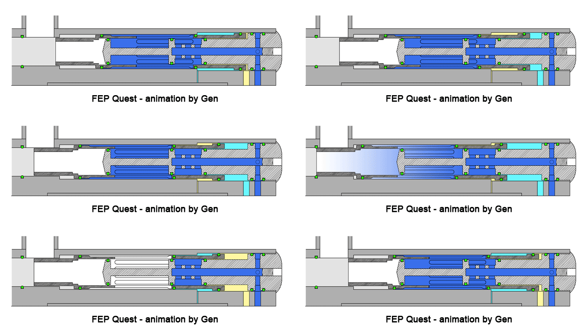
Heres an animation of a spool valve in operation.

Image

Obviuosly there are differences with that and mine, mainly being the spool valve chamber is not filled through the guide rod.

All parts are off the shelf parts that will be slightly modified, nothing is high precision - aka theres a lot of give with your dremeling.

sofar only 2 yes's?? we'll see how many this gets. :)
socoj2
Specialist
Specialist
Posts: 169
Joined: Fri Jun 29, 2007 9:17 am

Mon Jul 28, 2008 6:37 am

Mine shoots 4 shots a second. and thats only due to the feed mech. The new breach design. should be able to do 6. But after 6 shots i start to get shoot down unless i build a piston capable of 250 psi.

Currently i use 2x 1.5" pulse valves 2 QEVs and 5 regulators. to accomplish this.

Let me tell you. This is not cheap.

Mine is based on an eblade. so i actually have a ram and a bolt. and a bunch of custom electronics. i had to program.
I will need to fab a high flow 4 way to actuate the spool, as the high volumes will need high flow to operate anywhere near fast enough.
Unbalanced spool uses a 3way *ION. balanced spool would need a 4way *Shocker. No reason to make a balanced spooler for this. And a 1/8th Solenoid piloting a 3/8s QEV would be more then enough and a whole lot simpler.

I thought about doing a spooler for mine, but the Auto Cocker was just so much simpler.
Last edited by socoj2 on Mon Jul 28, 2008 9:32 pm, edited 1 time in total.
User avatar
POLAND_SPUD
Captain
Captain
Posts: 5402
Joined: Sat Oct 13, 2007 4:43 pm
Been thanked: 1 time

Mon Jul 28, 2008 7:46 am

I like the idea.. it's sound and all... but making this work is going to be a PITA... plus it's going to be expensive

but I wish you luck... (you are going to need it)
Children are the future

unless we stop them now
newbmatic
Private 2
Private 2
Posts: 34
Joined: Sun Jul 13, 2008 5:17 pm

Mon Jul 28, 2008 8:40 am

gun sounds really interesting, but about how long do you think is gonna take and how much r u gonna spend on it?
User avatar
MaxuS the 2nd
Corporal 2
Corporal 2
Posts: 674
Joined: Sat Jan 19, 2008 3:59 pm

Mon Jul 28, 2008 11:55 am

mobile chernobyl wrote:Time or Money?

If layed out correctly, Not much of either.
Did you not realise that I had already asked that question?
Badman
User avatar
mobile chernobyl
Corporal 3
Corporal 3
United States of America
Posts: 756
Joined: Sun Dec 03, 2006 11:53 am
Been thanked: 7 times

Mon Jul 28, 2008 12:28 pm

Maxus the 2nd - Your wording is dodgy. Do you want a more specific answer or are you looking for something else? I'll admit it, you caught me, I do plan to spend 15 chilli-dogs and a case of pepsi on it.

POLAND_SPUD and newbmatic - It probably will be a PITA, I will spend more time tuning it than I will of drawing and fabricating combined. It's just the nature of the beast. Cost should be low, all the fittings are readily available, and there is very little that can't be bought locally for me. O-Rings may need to be ordered from McMaster.com so I can ensure a nice airtight, or somehting like it, operation. It will cost me multiple amounts more time than it will cost me in money, lets put it that way.

socoj2 - Your gun shoots four rounds per second? Cool. I'm probably way off in the ROF calculation, as I was doing that for my mini 1 gallon compressor (think snail pace recharge rate) and no accumulation resevoir. It will most likely be way higher (perhaps 20+ per minute, or more) but I'm not going to overestimate and be dissapointed. The reason I think the ROF will be low is because of the ammo, and bolt(spool) travel. To seal off the magazine from the barrel, the spool will need to travel 10". 10" can be traveled in .1s easily in a spud gun, but when your dealing with the mass the spool I'm designing will have, spreading the 10" of travel out over 1.5s puts alot less stress on the already inferrior PVC parts. To achieve the slower speeds, or rather adjustable speeds of the spool assembly, I will most likely have a second regulator controlling the spool so I can set the pressures around 40psi.
-And if you could please delete your animations of marker animations from ZDSPB.com, that would be appreciated. I posted the Quest becuase it is the most similar to my design. I am well aware how the markers you posted operate, and the differnce betweene balanced and unbalanced spool valves as I have owned 3 of the 5 markers you posted (even the older banzai green eclipse shocker turbo!). I've also done work on all the markers except the dangerous power (I like that design btw, for paintball).
-Sadly, your argument about not needing a balanced spool is flawed immediatly when you take a step back and look at our hobby we're participating in. Do we even need semi automatic spudguns??? No. You get the point :wink:
-Your using 4 valves and 5 regulators for your design? Interesting. Do you mind posting a link to this gun. I plan to use 1, maybe 2 regulators (two only if I want to regulate the pressure used to move the spool, similar to an LPR on todays pneumatic PBguns) and a large 4 way valve. The 4 way valve may be operated by a smaller ram and 4 way as well to have it fully autonomous... or not. It is a balanced design, so I technically could just operate it by hand as well, since it shuts off air chamber flow before it fires - meaning a dwell time argument is null.

I guess theres enough interest now, I'll work on sketching something up tonight in solidworks, and possibly animating it, so its easier to understand (well easier than essentially a napkin drawing haha).

Thanks for the luck wishes all, this one is definatly on the back burner for now 8)
socoj2
Specialist
Specialist
Posts: 169
Joined: Fri Jun 29, 2007 9:17 am

Mon Jul 28, 2008 1:31 pm

Well my source is a 3k-4500 psi scuba.

I have a LP reservoir that is 18" of 4" pipe that i run at 125 PSI.

I have moded one of the 1.5" pulse valves with a QEV, regulator and solenoid so it works as a 1.5" Pulse Regulator, So i can fill my primary chamber in under 75ms.

The Efficiency is Horrible. but as the tank i run in has 4 Scuba's it wasnt one of my design concerns.

Operating pressure is about 50 PSI
User avatar
mobile chernobyl
Corporal 3
Corporal 3
United States of America
Posts: 756
Joined: Sun Dec 03, 2006 11:53 am
Been thanked: 7 times

Mon Jul 28, 2008 2:57 pm

Haha wow 4 scuba tanks worth of HPA. that should last a while. I will most likely be aquiring a 10-25 gallon compressor soon. I mean I better at least, 10 gallons not going to be fun to fill after like a day.

Do you have a diagram of your design? Or was it made as you went along? Any time you go HVLP, the efficiency starts to tumble it seems. You use a valve to fill your chamber I take it? I would use a valve persay, the spool valve. I'm not sure of the port area of it yet, maybe I'll have that figgured out tonight. I do know it will be fed from a peice of 1.25" PVC however. Its recharge rate won't likely be that of yours.

The first project I want to do is figure out how to fab up air tight seals with 1.25" fittings as oring grooves on a stick of 1.25" pvc inside of a 2" PVC pipe, as that will be were a majority of the switching seals will be. I've done it before but It had a good amount more friction than I would like to have with this design because it was only a static seal.

Does anyone have a reccomendation of a lube that will help seal o-rings to the inside walls of PVC, but not break down either compound? I've actually heard waterbased works the best lol

::EDIT:: Oh yea, Socoj2 - I hate to be a nag but could you please delete your animations from your post. If you have to keep one, keep the shocker SFT as its the only one relevent to my design. Having all those animations clutters up a thread and just acts a "Kewl" bait.

Thanks man :)
Post Reply