Show us your pneumatic spud gun! Discuss pneumatic (compressed gas) powered potato guns and related accessories. Valve types, actuation, pipe, materials, fittings, compressors, safety, gas choices, and more.
-
Technician1002
- Captain

- Posts: 5189
- Joined: Sat Apr 04, 2009 11:10 am
Mon Apr 27, 2009 8:06 pm
jmccalip wrote:Thanks, but about the question on tee placement.
Is this layout OK?
I see a lot of people putting the tee on top, what is the reasoning behind that?
layout is OK, but it becomes a chamber sealer instead of a barrel sealer. The dead space is increased and there is a bend on the lower pressure side of the valve. Bends after the air expanded are not good and restrict the flow more than high pressure area bends.
Plug it into GGDT with the added dead space and chamber sealer instead of barrel sealer to see the change.
-
jmccalip
- Specialist

- Posts: 118
- Joined: Sun Apr 12, 2009 8:07 pm
Mon Apr 27, 2009 8:41 pm
Technician1002 wrote:
layout is OK, but it becomes a chamber sealer instead of a barrel sealer. The dead space is increased and there is a bend on the lower pressure side of the valve. Bends after the air expanded are not good and restrict the flow more than high pressure area bends.
Plug it into GGDT with the added dead space and chamber sealer instead of barrel sealer to see the change.
Thank you very much. I was a minute away from accidentally making it a chamber sealer.
I tried GGDT, but didn't see any change. The only way I got a change was by messing with the flow coefficient. But this doesn't matter, I will make sure it's a barrel seal.

Last edited by
jmccalip on Tue Apr 28, 2009 1:59 pm, edited 1 time in total.
-
Technician1002
- Captain
- Posts: 5189
- Joined: Sat Apr 04, 2009 11:10 am
Mon Apr 27, 2009 9:17 pm
jmccalip wrote:Technician1002 wrote:jmccalip wrote:Thanks, but about the question on tee placement.
Is this layout OK?
I see a lot of people putting the tee on top, what is the reasoning behind that?
layout is OK, but it becomes a chamber sealer instead of a barrel sealer. The dead space is increased and there is a bend on the lower pressure side of the valve. Bends after the air expanded are not good and restrict the flow more than high pressure area bends.
Plug it into GGDT with the added dead space and chamber sealer instead of barrel sealer to see the change.
Thank you very much. I was a minute away from accidentally making it a chamber sealer.
I tried GGDT, but didn't see any change. The only way I got a change was by messing with the flow coefficient. But this doesn't matter, I will make sure it's a barrel seal.
Did you plug in the two dead space values, one with the projectile very close to the valve and one an elbow away? The flow restriction after the valve isn't good. Lose the elbow and dead space after the valve if possible. Go full size into the valve instead of the smaller exit size.
-
jmccalip
- Specialist
- Posts: 118
- Joined: Sun Apr 12, 2009 8:07 pm
Mon Apr 27, 2009 9:57 pm
Technician1002 wrote:
Did you plug in the two dead space values, one with the projectile very close to the valve and one an elbow away? The flow restriction after the valve isn't good. Lose the elbow and dead space after the valve if possible. Go full size into the valve instead of the smaller exit size.
Lose the elbow? Huh? I can't take the elbow, I would have a cross shaped gun.
Here is what I have now:
I know the 4x2 reducer bushing is not efficient, I hope I don't lose much, but I already glued it and I made a mistake.
Last edited by
jmccalip on Tue Apr 28, 2009 1:59 pm, edited 1 time in total.
-
Technician1002
- Captain
- Posts: 5189
- Joined: Sat Apr 04, 2009 11:10 am
Mon Apr 27, 2009 11:10 pm
Very good moving the t and getting rid of the space between the valve and projectile.
Lose the elbow? Huh? I can't take the elbow
Just between the valve and projectile. Done. Looks good.
Have you modeled it in GGDT? Too bad you had to reduce before the valve.

2 inch flow is awsome. My avitar is the collision between an apple and a bottled water. It used a 2 inch valve. The water bottle and apple both exploded together on impact.
-
jmccalip
- Specialist
- Posts: 118
- Joined: Sun Apr 12, 2009 8:07 pm
Tue Apr 28, 2009 7:59 am
Technician1002 wrote:
Have you modeled it in GGDT? Too bad you had to reduce before the valve.
.
I have, and at 60psi it said a golf ball would go about 515fps. About the reducer before the valve, it's still larger than the barrel so shouldn't it should only affect air turbulence? I would assume a 4" chamber can still dump through a 2" opening pretty freakin' fast.
Edit: I decided I will just spend the ten dollars and replace the 4x2 with a 4x3. Problem solved. This thing is a money pit.
Last edited by
jmccalip on Tue Apr 28, 2009 1:58 pm, edited 1 time in total.
-
Carlman
- Staff Sergeant 2

- Posts: 1618
- Joined: Sat Nov 24, 2007 1:18 am
- Location: Western Australia
- Been thanked: 2 times
Tue Apr 28, 2009 10:21 am
Guys quote what you are replying to not what the person you are replying to was replying to and what they replyed to before hand.
Otherwise list the names and reply that way
Gets a bit much ya know?

Aussie spudders unite!!
-
jmccalip
- Specialist
- Posts: 118
- Joined: Sun Apr 12, 2009 8:07 pm
Tue Apr 28, 2009 1:42 pm
How do you people drill your equalization holes(yes I searched). There is not enough room to put a hole. The piston will be pressed hard against the barrel pipe, and I don't think the top seal will be able to lift up and let air by into the chamber.
-
Technician1002
- Captain
- Posts: 5189
- Joined: Sat Apr 04, 2009 11:10 am
Wed Apr 29, 2009 1:51 am
jmccalip wrote:How do you people drill your equalization holes(yes I searched). There is not enough room to put a hole. The piston will be pressed hard against the barrel pipe, and I don't think the top seal will be able to lift up and let air by into the chamber.
The seal on the face of the piston should not need a hole as it is there to just seal against the barrel. The eq hole is to provide a
small amount of leakage between the pilot area and the air storage area (chamber). I presume the photo shows the end facing the barrel. If this is the end facing into the pilot area, you may have a problem getting a good seal as when the pilot is vented, it may just bend the rubber over and leak huge amounts of air.
Could you provide a full picture of the piston and identify the surface that seals against the barrel? You don't want a leak into the barrel.
-
jmccalip
- Specialist
- Posts: 118
- Joined: Sun Apr 12, 2009 8:07 pm
Wed Apr 29, 2009 12:27 pm
Technician1002 wrote:jmccalip wrote:How do you people drill your equalization holes(yes I searched). There is not enough room to put a hole. The piston will be pressed hard against the barrel pipe, and I don't think the top seal will be able to lift up and let air by into the chamber.
The seal on the face of the piston should not need a hole as it is there to just seal against the barrel. The eq hole is to provide a
small amount of leakage between the pilot area and the air storage area (chamber). I presume the photo shows the end facing the barrel. If this is the end facing into the pilot area, you may have a problem getting a good seal as when the pilot is vented, it may just bend the rubber over and leak huge amounts of air.
Could you provide a full picture of the piston and identify the surface that seals against the barrel? You don't want a leak into the barrel.
Thanks. I'm at work right now, so this is the best picture I have.
In that picture I put the seal on the wrong side, but you get the idea.
-
Technician1002
- Captain
- Posts: 5189
- Joined: Sat Apr 04, 2009 11:10 am
Wed Apr 29, 2009 12:56 pm
jmccalip wrote:Technician1002 wrote:jmccalip wrote:How do you people drill your equalization holes(yes I searched). There is not enough room to put a hole. The piston will be pressed hard against the barrel pipe, and I don't think the top seal will be able to lift up and let air by into the chamber.
The seal on the face of the piston should not need a hole as it is there to just seal against the barrel. The eq hole is to provide a
small amount of leakage between the pilot area and the air storage area (chamber). I presume the photo shows the end facing the barrel. If this is the end facing into the pilot area, you may have a problem getting a good seal as when the pilot is vented, it may just bend the rubber over and leak huge amounts of air.
Could you provide a full picture of the piston and identify the surface that seals against the barrel? You don't want a leak into the barrel.
Thanks. I'm at work right now, so this is the best picture I have.
In that picture I put the seal on the wrong side, but you get the idea.
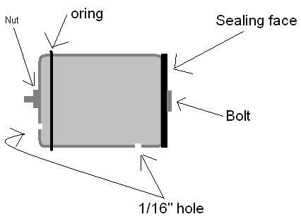
To fix that one with the barrel seal on the other end (away from the o ring) simply drill a small hole in the side on the chamber side of the o ring. Tilt it at an angle so the hole exits out the end where the rubber face is now. Or since you already have a hole in it for the bolt is to simply drill in the side to the center bolt hole that exits the pilot side of the piston.
In the photo attached, it shows a small piston being drilled near the sealing face through the piston all the way out the back. In your case it is OK to simply drill in the side and go under the O ring out the back. Use the smallest bit you have.
This makes a limited leak (on purpose) past the o ring from the pilot area to the chamber area.
-
Attachments
-
 Viewed 1880 times")
- New Mouse Musket piston getting it's EQ port
-
jmccalip
- Specialist
- Posts: 118
- Joined: Sun Apr 12, 2009 8:07 pm
Wed Apr 29, 2009 4:32 pm
Technician1002 wrote:
To fix that one with the barrel seal on the other end (away from the o ring) simply drill a small hole in the side on the chamber side of the o ring. Tilt it at an angle so the hole exits out the end where the rubber face is now. Or since you already have a hole in it for the bolt is to simply drill in the side to the center bolt hole that exits the pilot side of the piston.
In the photo attached, it shows a small piston being drilled near the sealing face through the piston all the way out the back. In your case it is OK to simply drill in the side and go under the O ring out the back. Use the smallest bit you have.
This makes a limited leak (on purpose) past the o ring from the pilot area to the chamber area.
Thanks for typing all that. I was hoping there would be a way to make the hole with a one way flapper(easy with a chamber sealer), but I guess not.
Unless I was to put a check valve on the pilot side of the piston...but I don't think it's worth the trouble.
Just to make sure. This is what you said?
-
Technician1002
- Captain
- Posts: 5189
- Joined: Sat Apr 04, 2009 11:10 am
Wed Apr 29, 2009 6:59 pm
jmccalip wrote:Technician1002 wrote:
To fix that one with the barrel seal on the other end (away from the o ring) simply drill a small hole in the side on the chamber side of the o ring. Tilt it at an angle so the hole exits out the end where the rubber face is now. Or since you already have a hole in it for the bolt is to simply drill in the side to the center bolt hole that exits the pilot side of the piston.
In the photo attached, it shows a small piston being drilled near the sealing face through the piston all the way out the back. In your case it is OK to simply drill in the side and go under the O ring out the back. Use the smallest bit you have.
This makes a limited leak (on purpose) past the o ring from the pilot area to the chamber area.
Thanks for typing all that. I was hoping there would be a way to make the hole with a one way flapper(easy with a chamber sealer), but I guess not.
Unless I was to put a check valve on the pilot side of the piston...but I don't think it's worth the trouble.
Just to make sure. This is what you said?

Perfect. It's OK to put the hole closer to the O ring. On my photo, I needed smaller flow so I used a longer hole to provide a capillary tube restriction. In your example the small drill bits are hard to find that long.
-
c11man
- Corporal 3

- Posts: 783
- Joined: Fri Feb 06, 2009 4:37 pm
- Location: Wisconsin, USA
Wed Apr 29, 2009 7:34 pm
i think that the last piston pic is going to work great
as for the hole you wont need a small drill bit. you could use a larger longer one to go from the back and then use the small drill bit to drill into the larger air channel
-
jmccalip
- Specialist
- Posts: 118
- Joined: Sun Apr 12, 2009 8:07 pm
Thu Apr 30, 2009 3:02 pm
It's finally coming together! I just need to make the wooden supports and I'll be done. My jigsaw is broken so this might take a while though...
I was testing the piston with only 15 PSI in the chamber, and when I pulled the trigger it let out a loud BOOM!!!. No funny noises or delayed hissing. It was instant. Good thing I had the bumper in there.
I'm going to attach a miniature sharpie to the bumper so I can see how much the spring compresses.