Here's a quick idea I thought of last night when I while I was studying. I made the design for a nerf gun that would use a regulated portable air tank, that I need to last for as many shot as possible.
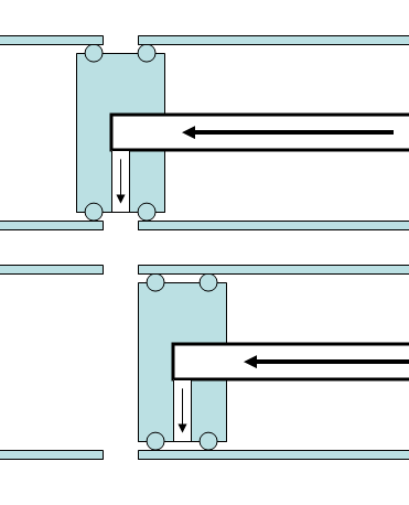
so we know that you can attach an regulated air input to a chamber and then use some auto loading system and then you got a semi automatic. to reduce the amount of wasted air we reduce the airflow (which makes the chamber fill slower) and remind ourselves to close the valve quickly (which leaves space for more human error), so I design this, to reduce the air flow to a minimum when our primary firing valve is open and increase flow when the chamber is pressurizing, all based on the pressure difference.
note: air input is coming from the right
Posted: Mon Oct 05, 2009 12:15 pm
by Technician1002
I like the idea. It's a crude variation of a mass flow controller. I was looking into a way to do full auto in an air cannon. The primary attack will be a relatively short dwell time to conserve air combined with a flow control so low pressure does not increase flow.
interesting, I don't know much about mass flow controllers, it looks like a really complex and expensive piece of equipment. if you used one of those you'd even need to have a power source for the circuit. you'd might as well just have an electronic cut off valve for your airsupply
For making an efficient automatic, qevs and 3way 2position actuator valves typically are the way to go. I designed this because I wanted to use a blowgun as my primary valve because it would have been cheaper, easier and smaller, but still relatively powerful for it's purpose.
Posted: Mon Oct 05, 2009 7:56 pm
by POLAND_SPUD
@tech
you could add an extra valve to you QDV cannons that will close of air flow when the the valve opens... you'd basically have a biga## spool/poppet valve - I don't think it can be simpler than that
plus you could also attach the bolt directly to the piston... and voila you've got semi auto gun
no offence... but I am surprised that even though you always talk about QDVs, you've never tried to improve the design as I suggested earlier...
if you could combine the QDV and spool valve into one valve you'd have a good excuse to talk about it more... (and to post more pics)
lol sorry for being ironic
Posted: Mon Oct 05, 2009 8:30 pm
by Technician1002
POLAND_SPUD wrote:@tech
you could add an extra valve to you QDV cannons that will close of air flow when the the valve opens... you'd basically have a biga## spool/poppet valve - I don't think it can be simpler than that
plus you could also attach the bolt directly to the piston... and voila you've got semi auto gun
no offence... but I am surprised that even though you always talk about QDVs, you've never tried to improve the design as I suggested earlier...
if you could combine the QDV and spool valve into one valve you'd have a good excuse to talk about it more... (and to post more pics)
lol sorry for being ironic
I was working more along the lines of the duty cycle. If the cannon valve is open for a maximum of 30ms and closed during the reload cycle for 500ms (2 shots/sec) the spilled air is less than 10%.
For the duty cycle, I was looking into using a small amount of piston blow by during the shot to enter the bumper area (traditional pilot volume) so when the tank is exhausted the piston would bounce and auto close. The trigger rod would need some modification to enable this, possibly eliminate the rod altogether and make the piston a linear electric motor and operate it with an electrical pulse. I have been playing with designs, but have been slow to post them as I do a sanity check on each.
For combining the piston valve with a fill spool valve, I've avoided this route for piston moving mass issues. It would slow the valve and the spool valve for the fill air would be a high friction item. Both these reasons are why it failed my sanity check.
Since most people don't understand a mass flow controller, without a cheezy drawing yet, I'll describe the basics.
If you take a regular regulator, it regulates with a diaphragm against a spring to provide an output somewhere above atmospheric pressure. One side of the diaphragm is vented to atmospheric pressure.
If the output of the regulator is fed through a metering orifice, at a set pressure you get a set flow. This works as long as the output is at atmospheric pressure. If we take the output after the metering orifice and tie it to the vent on the regulator so the pressure can build, the pressure cross the orifice remains stable so the flow is regulated over a wide output pressure range.
Posted: Mon Oct 05, 2009 9:02 pm
by POLAND_SPUD
it's a good idea to avoid electronics when they are not needed... it would be way better if the gun relied on air only.... I understand that you are probably pretty good at electronics but if you don't have to add something completely new to the design - it a good idea not to do it
also I don't really see any point in reducing amount of lost air when you can simply get rid off all loses with an fairly simple valve
It would slow the valve and the spool valve for the fill air would be a high friction item. Both these reasons are why it failed my sanity check.
and
a linear electric motor
hmmm... a linear electric motor... man that's just wrong... a pneumatic cylinder is all you need for this application and actually it would perform here better...
in the idea I proposed the QDV is opened via an air cylinder... the air cylinder is connected with the chamber and there is a simple 2 way valve (e.g. a blowgun) in between...
when you open that valve the cylinder retracts opening the QDV... as soon as it's open air from the cylinder flows back to the chamber and a spring return closes the QDV....
the only thing that you have to add to this is a simple valve that would open when the piston is in normal (closed position)... that could be something as simple as a blowgun...
Posted: Mon Oct 05, 2009 9:32 pm
by Technician1002
POLAND_SPUD wrote:it's a good idea to avoid electronics when they are not needed... it would be way better if the gun relied on air only.... I understand that you are probably pretty good at electronics but if you don't have to add something completely new to the design - it a good idea not to do it
also I don't really see any point in reducing amount of lost air when you can simply get rid off all loses with an fairly simple valve
It would slow the valve and the spool valve for the fill air would be a high friction item. Both these reasons are why it failed my sanity check.
and
a linear electric motor
hmmm... a linear electric motor... man that's just wrong... a pneumatic cylinder is all you need for this application and actually it would perform here better...
in the idea I proposed the QDV is opened via an air cylinder... the air cylinder is connected with the chamber and there is a simple 2 way valve (e.g. a blowgun) in between...
when you open that valve the cylinder retracts opening the QDV... as soon as it's open air from the cylinder flows back to the chamber and a spring return closes the QDV....
the only thing that you have to add to this is a simple valve that would open when the piston is in normal (closed position)... that could be something as simple as a blowgun...
Ever watch a speaker cone move? Ever watch a disk drive head positioner operate. An air cylinder is several orders of magnitude slower. I'm aiming for a fast dwell time. The blowgun/air cylinder arrangement though functional would be operational more like the fully automatic tennis ball launcher in another recent thread.
Acceleration time of the linear electric would be measured in parts of a ms. Once accelerated, the valve would finish the stroke on balistics and normal QDV operation and re-closed by rebound without any need to reverse an air cylinder. Remember, I am designing for several rounds/sec.
I am looking at having the amount of "lost air" being less or a negative number by having the QDV re-close prior to the cylinder fully reaching 0 PSI. I may save more air with a fast re-close than by preventing all inlet air flow during the shot. An additional air savings is there will be no air lost to the air cylinder.
With the right projectile, pressure and fingertip operation of the trigger, I'm already achieving a fast enough rebound close on my piston to retain up to 15 PSI of the chamber pressure. Removal of the control rod and adding a shorted turn winding to the piston for repulsion drive, i may be able to speed it up.
Posted: Tue Oct 06, 2009 8:27 pm
by iknowmy3tables
i'm really confused,
Technician why exactly are you so interested in a making an input fill valve independent from the pilot valve?
what's wrongs with a 3way 2poistion pilot valve and a good ole' pilot operated valve like a homemade piston, diaphram, or purchased qev. this 3way pilot system waist virtually no air (unless you count the pilot volume), after the pilot valve is closed the air immediately starts to flow in through the pilot volume closing the piston or diaphragm, this means that the valve doesn't need to rely on having a constant tension force on the diaphragm/piston like the spring you find in sprinkler valves that make the valve more resistant to open thus it opens slower, and the so since the oncoming air enters through the pilot the pressure in the pilot volume is always greater than or equal to the chamber volume so you can fill the system faster than you could with the input directly attached to the chamber.
Posted: Wed Oct 07, 2009 3:10 am
by POLAND_SPUD
did you mean 'inflaytion' ??
[youtube][/youtube]
Posted: Mon Oct 12, 2009 12:31 pm
by iknowmy3tables
okay, actully I don't want this to die because I REALLY want to know some other reasons as to why one might prefer a direct chamber input?
Posted: Fri Oct 30, 2009 5:39 am
by iknowmy3tables
why didn't someone tell me that Technician was big with his mechanically actuated valves, don't you guys know that I'm no longer very active on this forum
well rather then making a smart input valve, I would recommend redesigning your current valve to do to things at once
one example
my pistion valve logic tells me that your orings on your valves could be much closer together, your piston doesn't need to open very far before dead space becomes a bigger factor than flow. and you could replace your center rod with a small fixed metal pipe to provide an air input and instead of making the rod slide make the knob slide. allow
Posted: Fri Oct 30, 2009 6:58 am
by POLAND_SPUD
wow that's ingenious
Posted: Fri Oct 30, 2009 9:55 am
by Technician1002
iknowmy3tables wrote:why didn't someone tell me that Technician was big with his mechanically actuated valves, don't you guys know that I'm no longer very active on this forum
well rather then making a smart input valve, I would recommend redesigning your current valve to do to things at once
one example
my pistion valve logic tells me that your orings on your valves could be much closer together, your piston doesn't need to open very far before dead space becomes a bigger factor than flow. and you could replace your center rod with a small fixed metal pipe to provide an air input and instead of making the rod slide make the knob slide. allow
I thought about that, but the solution to one problem makes 4 more.
1, The moving pipe with the piston adds moving mass. Result slower operation.
2 The moving rod needs seals, result more friction.
3 The rod distributes forces on the center of the piston assy. Result, extra stress on the piston concentrated on the center when the piston lands in the bumper. The current design has bumper behind most all of the piston area.
4 The small leakage path to allow loading of barrel tight projectiles is eliminated. Current design allows slow escape of trapped air for shooting apples and oranges.
The o rings are spaced on the current piston to span the gap of the ports. The ports are designed to have a larger total cross section than the cross sectional area of the outlet pipe. Moving the o rings close together will lower the piston mass but require a flow restricting port size. The port size was enlarged above bare minimum to cause low velocity in the area of the edges of the ports so there is little pressure loss in that area. I make my ports 1/2 the pipe diameter tall instead of the bare minimum of 1/4 the pipe diameter. This allows flow through the rectangular ports at Mach 0.5 while the air enters the outlet pipe at Mach 1.
Posted: Sat Oct 31, 2009 4:30 pm
by iknowmy3tables
The o rings are spaced on the current piston to span the gap of the ports. The ports are designed to have a larger total cross section than the cross sectional area of the outlet pipe. Moving the o rings close together will lower the piston mass but require a flow restricting port size. The port size was enlarged above bare minimum to cause low velocity in the area of the edges of the ports so there is little pressure loss in that area. I make my ports 1/2 the pipe diameter tall instead of the bare minimum of 1/4 the pipe diameter. This allows flow through the rectangular ports at Mach 0.5 while the air enters the outlet pipe at Mach 1.
I may need someone to confirm me on this but I believe that in most optimized conventional piston valves the distance the piston is allowed to move is much less than half that of the output diameter, and this is so because further allowed movement would increase the dead space which would hamper performance more than the increased amount of flow improve it, this may depend on the volume and barrel length but for the most part the optimized distence on chamber sealing pistons tends to be less than 1/3 of the orifice diameter and of course the the optimized distance on on barrel sealing pistons would tend to be less.
Therefore my judgment tells me that the optimized distance for the allowed movement of your piston for your can be less than it is without negatively affecting performance to significant extent, and since the distance of piston movement decides the minimum port size, and the minimum port size decides the minimum distance between orings, I believe the distance between the o-rings could be significantly decreased
#2 is not true according to my suggestion, my suggestion is that the rod is epoxied into the piston, and instead the handle that you pull is free sliding. I am suggesting a very small pipe that could be nearly as narrow
this may not be the best solution, but I believe you ought to choose some design that allows the input to be shut off when the valve is trigggered, btw how do propose you would make this valve design fully automatic? and if you have made or if you make thread for that could you link me too it?
Posted: Sun Nov 01, 2009 11:24 am
by POLAND_SPUD
I've got to say that your design is great... I mean it's much much better and simpler than what I proposed... just think how what cool guns you could build with it
2 The moving rod needs seals, result more friction.
you could use an airhose or flexible tubing instead of a rigid rod