Show us your pneumatic spud gun! Discuss pneumatic (compressed gas) powered potato guns and related accessories. Valve types, actuation, pipe, materials, fittings, compressors, safety, gas choices, and more.
-
Jack_Hogg
- Specialist

- Posts: 133
- Joined: Tue Feb 20, 2007 7:56 am
Thu May 06, 2010 1:59 am
It will be made out of a solid peice of 30×60×150mm Aluminium
Tell me what you think

40BAR
Proud member of the Dutch Spud Clan!
-
jackssmirkingrevenge
- Five Star General

- Posts: 26179
- Joined: Thu Mar 15, 2007 11:28 pm
- Has thanked: 543 times
- Been thanked: 321 times
Thu May 06, 2010 2:05 am
Jack_Hogg wrote:It will be made out of a solid peice of 30×60×150mm Aluminium

Looks like a sound design, I imagine the tolerances will be tight so no reason why it shouldn't work very well.
hectmarr wrote:You have to make many weapons, because this field is long and short life
-
Jack_Hogg
- Specialist
- Posts: 133
- Joined: Tue Feb 20, 2007 7:56 am
Thu May 06, 2010 2:08 am
Ok, are there any things you would have changed? Like the size of the holes, or the end plug or something? I want it to be compact as pissible. A bulpup design.
40BAR
Proud member of the Dutch Spud Clan!
-
Jack_Hogg
- Specialist
- Posts: 133
- Joined: Tue Feb 20, 2007 7:56 am
Thu May 06, 2010 2:16 am

No. It's just a scetch. I still have no dimensions. Do you have suggestions on some dimensions?
EDIT
Barrel will be 12mm copper tube (10mm id) resevoir will be 1" 300mm pipenipple. Ballvalve will be ½
40BAR
Proud member of the Dutch Spud Clan!
-
jackssmirkingrevenge
- Five Star General
- Posts: 26179
- Joined: Thu Mar 15, 2007 11:28 pm
- Has thanked: 543 times
- Been thanked: 321 times
Thu May 06, 2010 2:35 am
w-a-a-a-a-a-i-t a minute.
As it is the design won't work.
The piston can't de solid, otherwise there will be no place for the chamber pressure to open it once the pilot empties.
-
Attachments
-
- pistonmod.gif (4.89 KiB) Viewed 2924 times
hectmarr wrote:You have to make many weapons, because this field is long and short life
-
Jack_Hogg
- Specialist
- Posts: 133
- Joined: Tue Feb 20, 2007 7:56 am
Thu May 06, 2010 2:44 am
Hmm I really have a hard time understanding this..
The pressure behind the piston is equal to the chamber pressure. Once the pressure is released behind the piston, the piston will move down am I right?
40BAR
Proud member of the Dutch Spud Clan!
-
jackssmirkingrevenge
- Five Star General
- Posts: 26179
- Joined: Thu Mar 15, 2007 11:28 pm
- Has thanked: 543 times
- Been thanked: 321 times
Thu May 06, 2010 2:59 am
Look at the diagram, once you empty the pilot, what force is going to open the piston?
-
Attachments
-

- imhavingahardtimeunderstandingthis.gif (5.02 KiB) Viewed 2911 times
hectmarr wrote:You have to make many weapons, because this field is long and short life
-
Jack_Hogg
- Specialist
- Posts: 133
- Joined: Tue Feb 20, 2007 7:56 am
Thu May 06, 2010 3:20 am
Now I get it! Thanks!

EDIT:
I placed the ¾" tap in the middle of the piece. Will the sides hold 60bar?
It's about 1,5mm on each side

EDIT #2
I made a scetch of the dimentions. What do you think?

40BAR
Proud member of the Dutch Spud Clan!
-
POLAND_SPUD
- Captain

- Posts: 5402
- Joined: Sat Oct 13, 2007 4:43 pm
- Been thanked: 1 time
Thu May 06, 2010 6:54 am
hmm this looks interesting... can to us something more about the design, I mean what sort of pressures are we talking about??
also that looks like a buttstock... that's pretty cool but it means that the BV will be very close to your shoulder... I mean much too close
Children are the future
unless we stop them now
-
Jack_Hogg
- Specialist
- Posts: 133
- Joined: Tue Feb 20, 2007 7:56 am
Thu May 06, 2010 7:14 am
POLAND_SPUD wrote:hmm this looks interesting... can to us something more about the design, I mean what sort of pressures are we talking about??
also that looks like a buttstock... that's pretty cool but it means that the BV will be very close to your shoulder... I mean much too close
The pressure I want to use is 50 to 60 bars. That's about 700 to 870 PSI.
You are right about the buttstock. I am planning to build a spring assisted ballvalve.
40BAR
Proud member of the Dutch Spud Clan!
-
POLAND_SPUD
- Captain
- Posts: 5402
- Joined: Sat Oct 13, 2007 4:43 pm
- Been thanked: 1 time
Thu May 06, 2010 7:27 am
may I suggest building a spool valve design ??
in this way you could pilot the valve using lower pressures
-
Attachments
-
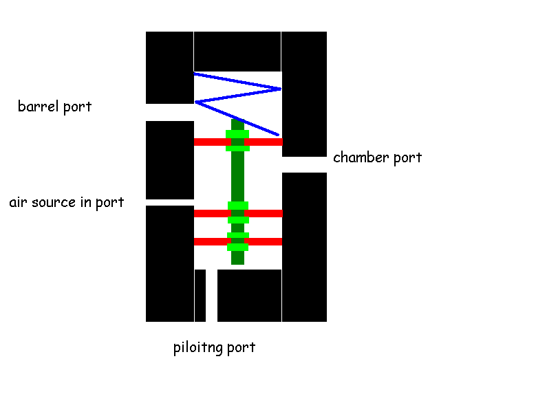
- of course you can have all the ports on one side of the block...
- positive pressure valve.PNG (16.38 KiB) Viewed 2866 times
Children are the future
unless we stop them now
-
Crna Legija
- First Sergeant 2

- Posts: 2333
- Joined: Sun Jul 20, 2008 5:14 am
- Location: australia
Thu May 06, 2010 7:57 am
lol running low on paper, i think that you should use a solenoid valve to pilot it to keep a clean look or even a real small QEV like the ones on paint ball guns
'' To alcohol... The cause of, and solution to, all of life's problems.”
--Homer Simpson
Add me on ps3: wannafuk, 8/11/11 cant wait
-
POLAND_SPUD
- Captain
- Posts: 5402
- Joined: Sat Oct 13, 2007 4:43 pm
- Been thanked: 1 time
Thu May 06, 2010 9:45 am
ohh yeah or you might as well mount a small QEV instead of the bv and a QDV... though that goes without saying
Children are the future
unless we stop them now
-
Technician1002
- Captain
- Posts: 5189
- Joined: Sat Apr 04, 2009 11:10 am
Thu May 06, 2010 11:59 am
This design can most certanly work. What the drawing does not show properly is the location of the barrel seal and it's diameter. If the seal is on the OD of the piston, then absolutely it won't work unless converted to a manually opened QDV. There will be no force to open the piston once the pilot is vented.
If there is no seal from the chamber forward so air pressure is on part of the face of the piston and the seal is at the end of the barrel, then there will be pressure on the piston face to open it. The big problem is there is not enough space to keep this pressure on the face of the piston so when it cracks and the piston face pressure vanishes out the barrel, it will stop opening. A piston with a step down in size to permit air into the piston face area will work fine.
Edit, edited the drawing to show the change.
Extending the valve seat closer to the air chamber would improve the performance.
Edited again to show the extended valve seat which results in a shorter ligher piston and better flow to the face of the piston when it opens. All good things.
-
Attachments
-
- Modification to show new seal area on the barrel. It is not able to have pressure to open.
- imhavingahardtimeunderstandingthis_436.gif (4.16 KiB) Viewed 2805 times
-
- 2nd image edit to move the valve seat and show the face of the piston with pressure to open it.
- imhavingahardtimeunderstandingthis_436.gif (4.18 KiB) Viewed 2800 times