Page 5 of 9
Posted: Tue Jan 01, 2008 9:07 pm
by sandman
size?
flow coefficient?
Posted: Tue Jan 01, 2008 9:53 pm
by clide
Nope, changes in surface area exposed to pressure is what makes them fast, and being fast is what gives them their performance. I've built my share of experimental valves, and I've got to agree with Rag, this factor is very important. Any valves I built that neglected it were either complete failures or huge disappointments.
Posted: Tue Jan 01, 2008 11:51 pm
by jackssmirkingrevenge
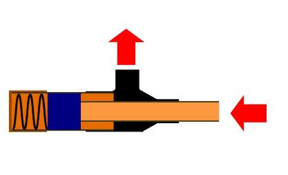
Fair points, how about this then?
Posted: Tue Jan 01, 2008 11:56 pm
by MrCrowley
If you get the right springs I don't see why not, hotwireds design looks easier to make and only one spring to calibrate. (well find the correct one)
Actually with HotWired's design, as soon as the spring returns the top piston down and the bottom piston moves down with it, for the air to seep past...
Wont it just push the top piston back up which will move the bottom piston up blocking the air flow and minimizing the air pressure inside of the chamber

As soon as a tiny amount of air is in the chamber it will block of the air flow as the pistons move up.
Posted: Wed Jan 02, 2008 12:06 am
by jackssmirkingrevenge
What I don't like about hotwired's design is the fact that it's got two coaxial pistons joined by a shaft, if not aligned well the thing can easily lock up and with my construction methods it's not something I can guarantee. Also, it involves sealing a vent within a tube, something which can be done (look at any chamber sealing piston valve) but personally I'm not too keen on.
Posted: Wed Jan 02, 2008 2:40 am
by Hotwired
Mrcrowley, the spring does two things, at first it's there to compensate for the area difference between the pistons.
So until the pressure builds up so the force difference between the piston faces overcomes the spring it stays shut.
JSR, how about not constructing a custom chamber and using standard piping?
No epoxying the thing together for life either


Maintenance plug at one end, through which the whole piston assembly and spring can be slid out. I hope that relieves at least some worries of a sliding system locking up.
Made it from standard copper diagram bits because thats generally what I have lying about in my paint sketchpad.
Posted: Wed Jan 02, 2008 3:10 am
by jackssmirkingrevenge
I learnt from v2.0 that adding a threaded cap for maintenance is a big plus, especially in these systems where you'd need to adjust spring length and compression.
While your design works well in theory, I still think that
this is a more practical proposal in terms of construction, plus it guarantees a 100% seal on the airflow without adding any friction.
I'm back at work already so the furious rate of prototype production will probably subside somewhat, at the same time I'm also conteplating hammer valves as well as revisiting the preloaded cartridge idea - I still want to see that spent brass fly one day

edit: I'm liking the idea of an externally cocked hammer, as an simplified adaptation of the design proposed
here, what about this?
Posted: Wed Jan 02, 2008 8:05 am
by SPG
Hotwired wrote:Oh come on.
Just tried a couple of RC engine pistons - lovely tight seal and easy movement. I'm now convinced, and take back earlier worries.
Now to work out how to join that up to an autofeed system.
Hotwired wrote:JSR, how about not constructing a custom chamber and using standard piping?
No epoxying the thing together for life either
Maintenance plug at one end, through which the whole piston assembly and spring can be slid out.
Just a thought on that one, why not put a schraeder in your maintenance plug instead of a spring and pre-pressurise the area between it and the output piston to the chamber pressure you want.
Posted: Wed Jan 02, 2008 12:23 pm
by Ragnarok
I still think Hotwired's design, although it will work, will have limited power.
I had many of these same issues when I was designing the mechanisms for my automatic combustion design, but I found a way around that, and the design should work if I ever build it.
People HAVE to start thinking more like chamber sealer piston valves:
When that opens, it exposes extra area, a surefire way of creating the extra force to open the valve seriously fast and dump the volume of air required.
When the pressure drops low enough, the spring will push the piston back into place, and when it reseals, the area is now much lower, so that it won't immediately be pushed open again.
That sort of thing is what will create the difference between opening and closing pressures that will put a stop to a valve finding an equilibrium at constantly half open.
This will still need some variables to be controlled to avoid it finding an equilibrium in closing, but that's an easy part - it could also be combined with a modified form of Hotwired's concept to get the best out of it.
I might even create a version of the design myself when I'm completely happy with it to test it out.
Posted: Wed Jan 02, 2008 12:35 pm
by Skywalker
Hmm, interesting Rag. Seems like it would need a pulse of pressure from the supply side to break the valve wide open. Unless you have practically a pinhole-sized restriction on that exhaust port, leakage will occur around the seal and out the exhaust without pressurizing that volume and causing the piston to move back and open fully.
You are spot-on in your diagnosis of the problem with the equilibrium problem. I've had a hard time trying to explain it correctly.
Posted: Wed Jan 02, 2008 12:47 pm
by Ragnarok
Skywalker wrote:Hmm, interesting Rag. Seems like it would need a pulse of pressure from the supply side to break the valve wide open.
No specially created pulse would be needed if the spring were correctly chosen. The valve starting to open will create that pulse of force to slam it open itself.
Unless you have practically a pinhole-sized restriction on that exhaust port, leakage will occur around the seal and out the exhaust without pressurizing that volume and causing the piston to move back and open fully.
Again, it's really just a cross between a pop-off and a chamber sealer piston valve, which both work fine in their own way, with or without a such a restriction.
Posted: Wed Jan 02, 2008 12:51 pm
by jackssmirkingrevenge
You need to have the flow blocked off for sufficient pressure drop to reseal the valve, hotwired had the right idea there.
Posted: Wed Jan 02, 2008 12:57 pm
by Ragnarok
Indeed, flow would need to be restricted in some way, but I've engaged lazy mode and CBA to draw it combined with Hotwired's idea.
Posted: Wed Jan 02, 2008 5:43 pm
by Skywalker
Here's my version of the smash-up of Rag +Hotwired's ideas:

Does that look right? (I know I left out the action/loader, too lazy). I think it would work, although the length of that threaded rod will need to be tuned just right (shouldn't be too hard, just run it in or out of the piston using the nuts.) Also, probably want something more convenient than a ballvalve, maybe with some flow restriction.
With this, the 'poke-open' valve will necessarily be opening just before the piston seats (since it's a seat-seal, not a sliding seal), so there is a chance that this could hang. That could be solved by switching some things up and making a sliding seal there, but that would increase the complexity and difficulty of manufacture.
Posted: Wed Jan 02, 2008 11:47 pm
by jackssmirkingrevenge
That looks about right, what I don't like however is that air is released the moment the piston moves back. Personally I would modify it slightly like so: