Page 2 of 8
Posted: Sat Mar 22, 2008 1:46 am
by scottcrete
what does coaxial combustion mean?
Posted: Sat Mar 22, 2008 1:54 am
by starman
Some nice planning there. With the relatively short barrel it won't be an optimum performer velocity wise, but it will look good and be plenty LOUD. Keep up posted on your progress.
scottcrete wrote:what does coaxial combustion mean?
Your barrel looks like its running down the center and most of the length of the combustion chamber, a little unusual for a combustion. This configuration is mostly used in a pneumatic model.
Are you using hairspray for fuel? You going to have to unscrew the cap to air out each time. You could replace that with a ball valve and metered propane...you'll like it much better.
Posted: Sat Mar 22, 2008 2:01 am
by scottcrete
i want it to be loud as fudge.. lol and have a good flame come out of it.. i wont be shooting for distance.. just for boom.. wholy shite did you hear that... that is awesome effect... lol..
Posted: Sat Mar 22, 2008 2:07 am
by Novacastrian
scottcrete wrote:what does coaxial combustion mean?
A coax combustion is simply a combustion that throws away elbows and such and places some of the barrel inside the chamber, in effect reducing barrel length and decreasing chamber volume. It can be very handy for breech loading without the loss of dead space, i.e. load it through the ass end.

Posted: Sat Mar 22, 2008 2:22 am
by scottcrete
thanks.. man.. had no idea.. what that meant.. im a grunt.. lol
Posted: Sat Mar 22, 2008 8:44 am
by TurboSuper
Posted: Sat Mar 22, 2008 9:37 am
by bluerussetboy
Camera flashes work great if you don't try to over power them by adding more batteries and capacitors. The printed boards tend to arc and then burn up.
Another option is to keep the stock board and add an ignition coil. Use the search function of this forum, it has been discussed far too many times. It can also be found in the wiki.
This is what I tried to build last year. I found out I just didn't have the ability to build it from scratch. I ended up having a friend fix everything I forked up.

I used perfboard and wirewrapping originally, my buddy got rid of the wirewrapping and soldered everything.
Posted: Sat Mar 22, 2008 9:58 am
by scottcrete
thanks.. i was just (or also) wondering is it posibale to make this cicuit without the green stuff... or just without anything that will catch fire.. from over powering the board.. basically make my own board.. with only the essential parts neeeded. to make it work.,
your answer to that is?
thanks in advance
Posted: Sat Mar 22, 2008 10:40 am
by rp181
If the board keeps lighting on fire, then run solder over all the etched pcb lines. Make sure there exposed, they might be varnished.
Posted: Sat Mar 22, 2008 12:13 pm
by TurboSuper
Well the super-high voltage part (middle electrode) is what's really doing all the dirty work in terms of triggering. If you can somehow isolate that, you can just run heavy(er)-gauge wires right from the cap bank.
I still think it's kind of a moot point since one capacitor will get the job done just fine.
Posted: Sat Mar 22, 2008 1:05 pm
by jimmy101
scottcrete
Keep trying, you are getting close to getting your big-ass<sup>TM</sup> sparker to work.
What you are trying to do is get a "trigatron" to work. That is the tricky part. Your high voltage/power setup looks good. It is getting it to trigger that is hard. Generic switches will be melted into a blob of plastic and metal when used with the kind of power you are working with. The solution is the trigatron switch.
Take a look at the link turbospider posted
http://www.angelfire.com/80s/sixmhz/camera.html
or this one
http://www.angelfire.com/80s/sixmhz/trigatron.html
The spark gap setup should look like this one from sixmhz pages;
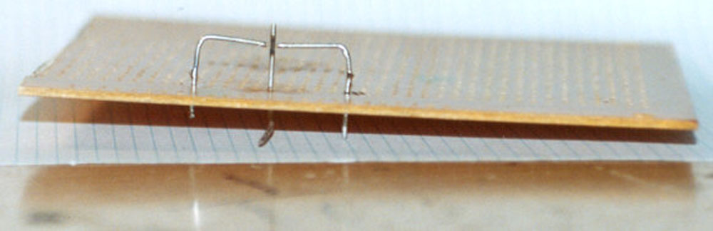
If you are just getting a wimpy spark then only the high voltage (couple KV) is actually sparking. The high voltage comes from the second transformer on your photoflash circuit board and it is the lead that was connected to the metal reflector around the flash tube.
You need to get the other two elctrodes closer to the HV electrode so that the small spark from the HV allows the much lower voltage (~300V), but much much higher power, from the photocap(s) to be discharged across the gap.
Got to get everything pretty close together. Pointy electrodes will help somewhat.
Once you get the spark gaps to work they'll tend to burn themselves up after a few uses so you might want to build it so thngs are adjustable.
Here is how I did it for a single photoflash board as a demonstrator. If you use fine thread drywall screws you can just screw them in as they burn up. Drywall screws have very sharp points, but they tend to get melted pretty quick. Make you connections to the screws with aligator clips and you can just replace the screws when they get to toasted.
Posted: Sat Mar 22, 2008 1:29 pm
by Hotwired
I'm amazed the circuitboard caught fire

I'd've liked to see that

Anyways, since I'm in a helpful frame of mind...
*fishes out a kodak board from a HUGE pile on desk*
...I'll do a chaotic walkthrough for that exact board :study:
Exactly the same board yup?

Now flip it over...

Pull off the pushbuttony thing you normally hold down to charge. Then solder a bit of metal across them so it's permanently connected. I was doing this quickly so I taped a tiny bit of wire wool across it...

Attach a few wires... (click for clarity)

Red and White coming in from the left are from the battery Red is + White is -
Yellow is attached to the CUT and stripped end of the short white wire from the little yellow transformer.
Green are attached to the capacitor terminals - positive and negative isn't important for them.
Black and White on the right are attached to a pushbutton switch which triggers the spark.
Now lets see what the green and yellow leads are rigged up to:

The GREEN leads are connected to two points held only 1-2mm apart.
The YELLOW lead is connected to a small loop of wire that goes around the gap between the two points - it does not touch either.
Right. When I push the pushbutton it makes a high voltage pulse go through the YELLOW lead and ionises the air around the little loop.
That lets a spark jump between the two green lead's points.
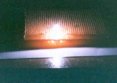
Ok, battery's connected and the capacitor's charged:
 So a demonstration clip to finish with
Edit: Waaaaah. Pipped by jimmy

Posted: Sat Mar 22, 2008 1:34 pm
by scottcrete
jimmy.. you are a god..
thank you.. I understand this in terms of
Trigitron for dummys!
lol.. you should write a book.. thanks for the help so much my friend.. but the next question i have it.. how do i make this circuit without the board catching fire?
Posted: Sat Mar 22, 2008 7:45 pm
by scottcrete
thanks you so much HOTWIRE.. what do i do about it catching fire though?
Posted: Sat Mar 22, 2008 8:07 pm
by jimmy101
Well of course the board caught fire, that's part of the "fun".
Actually, the board shouldn't catch fire. How many caps you got wired up to this thing right now? The copper traces on the board were designed to handle the current from a single cap, if you've got several caps all slaved to the same board then ... who knows what'll happen.
Can you take a picture of what you've got setup right now? Kind of hard to debug without a better idea of what you've got.
BTW, what is this beasty for? A single board and photocap is more than enough to fire a combustion spudgun. A working trigatron powered by a single photocap sounds like a cap or a small firecracker when it goes off. That's about a zillion times more energy than you actually need to ignite a combustion spudgun.
Are you trying to make a thermal gun?