


I was just trying to convince someone to be extremely careful as he wants to attempt feeding 40bar into a fridge compressor (testing to failure) to determine if by using two in series he could add up the output pressures.
So I happened to read through maggotman's thread again, and realised there were few things that seemed strange to me.
Granted, the pictures of the post mortem dissection of the compressor don't seem to appear any more which might explain why I am missing something here.
There was mention of his case not being pressurised at any point. As far as I am aware the compressor outlet goes strait out through small diameter steel or copper pipe but the inlet just feeds into the case. I have trouble picturing how the inlet could not pressurise the case, unless of course there is some other smaller casing with a seal around the motor shaft or something (Psycix suggested machining a part to fill that role iirc).
Another point is even if the compressor initially reached ~68bar (1000psi) where did the remaining 55bar needed to reach 1800psi come from (or even the 32 needed to get to 100bar) ?
Pressures should only add up, if the compressor can achieve 68bar in a standard atmosphere, shouldn't it only reach 100bar if it is placed in a 32bar relative atmosphere?
It was mentioned that he was using his normal compressor, which if indeed is a "normal" compressor shouldn't be able to output anywhere near the required pressure.
I do realise that the compressor apparently when very quickly from 1000 to 1800psi so maybe it was just working harder than usual going higher than its nominal max pressure.
And even with a high pressure compressor or fridge compressor, if the shell ever got pressurised, I am surprised it didn't fail. I remember seeing a post by Technician1002, in which he had found some fridge compressor specifications or failure reports stating much lower failure pressures.
What am I missing here ?
Another fridge compressors in series thread...

No. The limit on pressure is not necessarily because of the force the motor can muster. There are two limits on pump pressure. One is force that can be exerted, the other is dead volume in the pump.al-xg wrote:Pressures should only add up, if the compressor can achieve 68bar in a standard atmosphere, shouldn't it only reach 100bar if it is placed in a 32bar relative atmosphere?
The dead space in the compressor pump means that theoretically, it can muster a higher pressure gain if the input pressure is higher.
If I have a pump which can exert infinite force, but which has 1/30th dead volume, it's limited to (ignoring adiabatic heating) going from 1 atmosphere up to 30 atmospheres - a 29 atmosphere gain.
Put in 4 atmospheres, and its limit is then 120 atmospheres. 116 atmosphere gain.
You need to have both things in consideration. While your statement is true when the force exerted is the limit, it is not true when the dead volume is the limit.
Does that thing kinda look like a big cat to you?
Aha yep simple, thanks. 
But is the the case in a fridge compressor ? explaining why the piston/cylinder assembly broke before the motor staled or the power transmission link broke ?
The compressor motor does seem to struggle when getting towards high pressures would that happen as early without any dead space, or is it somehow linked to reaching the max pressure?
More importantly have I missed this same discussion somewhere else before I carry on posting in a new thread ?
-
Technician1002

- Captain

- Posts: 5189
- Joined: Sat Apr 04, 2009 11:10 am
For a quick dynamic on what happens, remember that air compresses. Take a bike pump and close off (seal) the outlet. Take a down stroke. At 15% travel the air compresses to 1/2 the space or double the pressure (not counting heating) so 1 atm becomes 2 atm or 15 PSI gauge. Now finish the stroke all the way to the bottom and figure the pressure.
In a cascaded compressor set up, (assume outlet sealed until the piston pressure = outlet pressure) feeding in say 10 bar (11 atm) becomes doubled at 1/2 stroke or 22 atm (21 bar). At 3/4 stroke and above the crank has severe force on it much like you experiance with a bike pump in the last 10% of the stroke. This can and does break things. Often it is a head gasket, but sometimes the connecting rod goes first as it is not intended for that force.
As for the compressors in cascade, we are not running a series of water pumps. Air compresses. The volume on the second compressor is not smaller than the first (assumming a pair of frigies) so it is NOT a case of compressor bumps to 100 and compressor 2 bumps it up to 200. Watch the volume as you compress to say 7 bar (100 PSI roughly) and then feed that into another compressor with the exact same displacement. To get the 7 bar into the second compressor, you will need 7 compressors in parallel to provide the volume. Now the lone 2nd stage compressor is trying to run up the pressure by the same ratio, but it doesn't have 7X the motor pushing it. This is why it is straining.


Let me share my knowledge:
Pressurized inputs.
The inlet is a tube connected to the case. Feeding air into a fridge compressor feeds into the case, pressurizing it. The compressor has a separate intake to suck air from the case into the cylinder.
The outlet is a small copper tube, spiraling around to make sure its flexible enough allow the compressor to move inside the case. This is because the compressor is resting on springs inside the shell. This is done to avoid vibration of the shell, making the compressor silent.
Other compressors, like screw type ones may be different!
Dead volume
They have minimal dead volume. The flat piston head levels with the machined surface of the cylinder body. On top of that is a machined plate with the check valves. They are reed-style valves with minimal dead volume.
After a very rough calculation using guessed values, a compressor should be able to reach more then 100bar assuming dead volume is the limiting factor, without a mechanical failure or motor stalling.
Cascading
I estimate the shell of a compressor to fail in the 25-50 bar region. Personally I would never pressurize it above 10 bar.
Note that pressurizing the input also puts pressure on the back of the piston! The nett force is the same!
However, when the air is compressed, the pressure rises faster than when compressing atmospheric pressure, where most of the distance traveled is done with low pressure.* This will require more power from the motor, and assuming the motor will give the same amount of power, lower the RPM.
Overpressure can bend the axis or crank mechanism, or stall the motor.
I think a single compressor has a higher chance to fail mechanically, while a cascaded one might fail earlier, due to the motor stalling.
*EDIT: While typing this whole story Technician showed this in more detail.
So, is 68+32= 100 correct?
That depends on what the compressor fails at when its at 68.
If the motor doesn't fail at 68+32 then it should be able to get to 100. If the motor stalls at 68, then it will stall at 68+something for sure and might not get to 100.
Pressurized inputs.
Yes, but keep in mind this is the case with reciprocating piston compressors. I have seen the insides of multiple compressors, and all are constructed as follows: (There may be different ones, of course)There was mention of his case not being pressurised at any point. As far as I am aware the compressor outlet goes strait out through small diameter steel or copper pipe but the inlet just feeds into the case. I have trouble picturing how the inlet could not pressurise the case, unless of course there is some other smaller casing with a seal around the motor shaft or something (Psycix suggested machining a part to fill that role iirc).
The inlet is a tube connected to the case. Feeding air into a fridge compressor feeds into the case, pressurizing it. The compressor has a separate intake to suck air from the case into the cylinder.
The outlet is a small copper tube, spiraling around to make sure its flexible enough allow the compressor to move inside the case. This is because the compressor is resting on springs inside the shell. This is done to avoid vibration of the shell, making the compressor silent.
Other compressors, like screw type ones may be different!
Dead volume
They have minimal dead volume. The flat piston head levels with the machined surface of the cylinder body. On top of that is a machined plate with the check valves. They are reed-style valves with minimal dead volume.
After a very rough calculation using guessed values, a compressor should be able to reach more then 100bar assuming dead volume is the limiting factor, without a mechanical failure or motor stalling.
Cascading
I estimate the shell of a compressor to fail in the 25-50 bar region. Personally I would never pressurize it above 10 bar.
Note that pressurizing the input also puts pressure on the back of the piston! The nett force is the same!
However, when the air is compressed, the pressure rises faster than when compressing atmospheric pressure, where most of the distance traveled is done with low pressure.* This will require more power from the motor, and assuming the motor will give the same amount of power, lower the RPM.
Overpressure can bend the axis or crank mechanism, or stall the motor.
I think a single compressor has a higher chance to fail mechanically, while a cascaded one might fail earlier, due to the motor stalling.
*EDIT: While typing this whole story Technician showed this in more detail.
So, is 68+32= 100 correct?
That depends on what the compressor fails at when its at 68.
If the motor doesn't fail at 68+32 then it should be able to get to 100. If the motor stalls at 68, then it will stall at 68+something for sure and might not get to 100.
-
Technician1002
- Captain
- Posts: 5189
- Joined: Sat Apr 04, 2009 11:10 am
Normal higher pressure compressors are multi stage. If you look at 2 stage shop compressors (140-180 PSI) they have 2 or 3 cylinders.
The 2 cylinder has one large cylinder with a large piston and long stroke feeding into a smaller cylinder with a small piston and sometimes a shorter stroke.
A finned tube or small radiator provides interstage cooling.
The displacement ratio between the two cylinders is in the 7:1 to 10:1 volume range. The two stages are not the same volume, but do require about the same HP.
A 3 cylinder version uses 2 large cylinders in parallel to feed into the single cylinder 2nd stage.
For higher pressure such as Paintball tank refills or SCUBA, a 3 or 4 stage compressor is used.
A typical 2 stage shop compressor is shown below. The second stage is smaller in diameter and sometimes has a shorter stroke. Finned tubing provides interstage cooling.
Last edited by Technician1002 on Mon Jul 12, 2010 1:04 pm, edited 2 times in total.


There are a few more things to consider. I looked at my mini-fridge and it expects the input pressure to be around 150PSI. If the inlet pressurizes the case, the case is at 150 PSI during normal operation.
When you feed a compressor input with compressed air, you effectively increase the volume of the stroke, so you will get more volume out
Depending on the construction of the compressor, pressurizing the inlet may actually add force to back of the piston, easing the motor's load somewhat.
When you feed a compressor input with compressed air, you effectively increase the volume of the stroke, so you will get more volume out
Depending on the construction of the compressor, pressurizing the inlet may actually add force to back of the piston, easing the motor's load somewhat.
POLAND_SPUD wrote:even if there was no link I'd know it's a bot because of female name
-
Technician1002
- Captain
- Posts: 5189
- Joined: Sat Apr 04, 2009 11:10 am
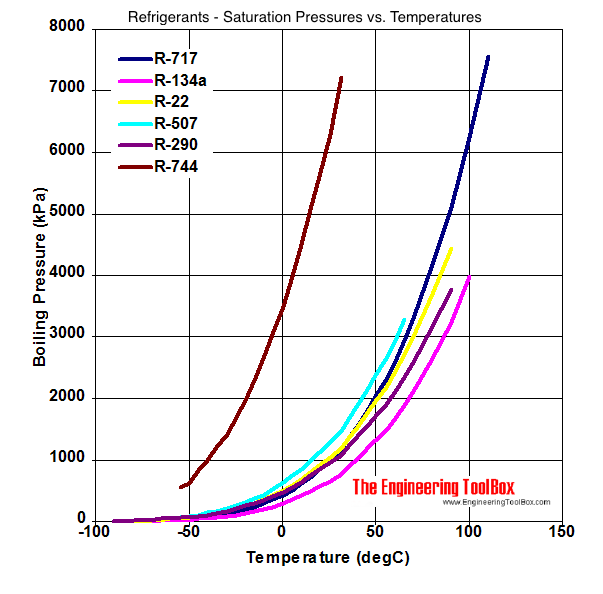
Pressure is dependant on temperature. In the case of a fridge the refrigerant boils at the inlet pressure. The colder it is in the fridge the lower the pressure. The number stamped on the compressor is for a warm fridge when it is first plugged in. After that the pressure drops with temperature. A refrigerant pressure chart will show the temperature pressure curve.ramses wrote:There are a few more things to consider. I looked at my mini-fridge and it expects the input pressure to be around 150PSI. If the inlet pressurizes the case, the case is at 150 PSI during normal operation.
Here is some common refrigerant boiling pressure temperature charts. Note the pressure is Absolute, not relative. R134a is common in fridges. R22 is common in airconditioners.
But the shell will still be required to withstand that pressure at some point. And is thus designed to be able to cope with that pressure. I would be more worried about overloading the motor than bursting the casing at pressures above 150 PSI.
POLAND_SPUD wrote:even if there was no link I'd know it's a bot because of female name
Wow a lot was covered there.
I'm guessing Tech meant 50% not 15%?Boyle's law doesn't work otherwise.
I think I had already gathered most of above, I should maybe have clarified further.
I was assuming a piston compressor using a cup seal on the piston, or a second check valve on the cylinder, but that in both cases pressuring the shell means that there is pressure on the back of the piston.
I was also assuming sufficient flow from the first compressor, ie a regulated buffer tank in between.
I understand multi-stage compressors (or think I do) but they don't tend to allow for back pressure on the piston. They are more a case of tiny piston for high pressure a load of larger pistons before it for higher throughput.
The main thing I was trying to determine was, if the dead volume isn't the limiting factor how did maggotman get those pressures ?
I'm not sure i got all of this
But forgetting dead volume, and in the case of a hand pump: If the "motor" (users arms) is able to pump to 11bar absolute pressure in a 1bar atmosphere, then if the atmosphere was 10bar he would reach 20bar and no longer be able to pump.
Hence the 68+32=100.
So If the series output is any higher than the sum of both separate outputs, dead volume must be the limiting factor.
As for the pressure rating of the casing, do you mean above 150psi ? Below would make much more sense to me. 150psi boiling pressure equates to ~40°C quite a hot fridge already.
40bar would be 100°C, I would expect safety factors but not a designed operating temperature of 100°C.
I'm guessing Tech meant 50% not 15%?Boyle's law doesn't work otherwise.
I think I had already gathered most of above, I should maybe have clarified further.
I was assuming a piston compressor using a cup seal on the piston, or a second check valve on the cylinder, but that in both cases pressuring the shell means that there is pressure on the back of the piston.
I was also assuming sufficient flow from the first compressor, ie a regulated buffer tank in between.
I understand multi-stage compressors (or think I do) but they don't tend to allow for back pressure on the piston. They are more a case of tiny piston for high pressure a load of larger pistons before it for higher throughput.
The main thing I was trying to determine was, if the dead volume isn't the limiting factor how did maggotman get those pressures ?
I'm not sure i got all of this
which is maybe where I'm going wrong.when the air is compressed, the pressure rises faster than when compressing atmospheric pressure, where most of the distance traveled is done with low pressure.* This will require more power from the motor, and assuming the motor will give the same amount of power, lower the RPM.
But forgetting dead volume, and in the case of a hand pump: If the "motor" (users arms) is able to pump to 11bar absolute pressure in a 1bar atmosphere, then if the atmosphere was 10bar he would reach 20bar and no longer be able to pump.
Hence the 68+32=100.
So If the series output is any higher than the sum of both separate outputs, dead volume must be the limiting factor.
As for the pressure rating of the casing, do you mean above 150psi ? Below would make much more sense to me. 150psi boiling pressure equates to ~40°C quite a hot fridge already.
40bar would be 100°C, I would expect safety factors but not a designed operating temperature of 100°C.
-
Technician1002
- Captain
- Posts: 5189
- Joined: Sat Apr 04, 2009 11:10 am
Maybe it will make more sense to place the bike pump, you, and some elbow grease inside a diving decompression chamber.
Outside the chamber at 1/2 stroke you reach 15 PSI.
Inside the chamber at 50 PSI (50 + 1 atm absolute) the 65 PSI absolute will go to 130 PSI at 1/2 pump stoke. Note this is with that easy nice pressure on the back of the piston to make it easy. Completing a full stroke will be serious work and could easly reach 400 PSI if your arms are strong enough. The change in pressure does more than add.
A 1/2 stroke is a boost of 15 psi outside. 1/2 stroke inside is a 65 psi boost. Guess which is more work to pump. It is not the one in the chamber with 50 PSI on the back of the piston.
Look at the change in VOLUME as the piston makes it's stroke. Then figure the pressure. A 100 PSI compressor feeding the input of another 100 PSI compressor does not = 200 PSI with both sharing the load.
The first compressor compresses 7X. to 7 Bar. (100 PSI or 8 Atm) the second compresses from 7 bar 7X or 8 atm 7 times to 56 ATM or 55 Bar, not 2X to 14 bar or 15 Atm. I hope this make more sense. Note to do this it requires much more force to pump the second stage unless the second stage is made much smaller in volume.
The above compression is for example only. A normal 2 stage compressor has less pressure rise per stage and normally outputs under 200 PSI for a shop compressor. The example shows 2 compressors cascaded with a 7X pressure rise on each stage for the sake of a possible 2 stage compressor application. This configuration will be fine for a delivery pressure between 150 PSI and 1,000. Single stage compressors are most often limited to 130 PSI. 3 or 4 stage compressors are used for SCUBA and Paintball applications.
The lack of pressure under the pressure on the latter stages is of little consequence as a flywheel momentum can take care of that detail. The horsepower required to keep it running at full output volume and pressure is the important factor. Too little of a motor for the higher pressure spells overload.
Working in absolute bar, the theoretical maximum pressure is the product of the compression ratios of all stages.
The force required is the on a given stage with pressure on both sides is the pressure differential across that stage times the cross section of that cylinder.
The volume moved by a stage is equal to the absolute pressure in bar (atmospheres, really) times the cross sectional area times the stroke of that stage.
So if the case never bursts, the motor will always be the limiting factor. That is to say that you can keep adding inlet pressure until the motor stalls or the case blows up.
You can't predict stall pressure simply by comparing the linear force available from the motor at a given displacement with the force on the piston at a given displacement (which increases somewhat exponentially, neglecting deadspace)
Because the pump has a flywheel with inertia, force required to not stall can (in the short term) exceed the force available at the motor at some displacements (which is NOT constant)
Thus, if flow through the inlet check valve is great enough, and there is only atmospheric pressure on the "back" of the piston, the inlet can actually transfer energy to the piston, accelerating it, driving the flywheel, and, if the motor can spin faster, ease SOME of the motor load. This will never be as good as if the "back" of the piston was connected to the inlet with a large buffer volume and near infinite flow, but it's better than nothing.
Similarly, if the back IS exposed to inlet pressure, and the inlet check valve in the cylinder head has insufficient flow, the motor will have to pull a pseudo-vacuum to prepare for the next stroke. If flow is poor enough, the pressure in the cylinder at the start of the next pump will be less than inlet pressure (and the pressure in the case), and the pressure in the case will drive the piston until the pseudo-vacuum has collapsed. This will drive the motor, but will also decrease the actual displaced volume and actual compression ratio.
*inhales* I think I earned my 5 spudbux for that one. I may dig up the BIG equations in my TI-84 with regard to all this. That will clarify things.
POLAND_SPUD wrote:even if there was no link I'd know it's a bot because of female name
I'm not sure the above example works if the motor has a defined max power. "Completing a full stroke" requires more power than available.
Ramses posted in between but if we agree on this:
500W is the max power, you might start off pumping faster while the pressure is low but you get to 1000N and trying to pump slower won't change anything the pump is holding you up off the ground. (equivalent to the motor stalling on a compressor)
No flywheels here.
The max pressure you can acheive on an ideal (no dead volume) pump with a 10mm dia piston is ~127bar.
Try the same thing with an 11bar absolute atmosphere, same as before, 10bar higher:
The pressure is acting on the other side of the piston providing a extra constant 78.5N added to the force you can apply to the pump shaft. 1078.5N on a 10mm piston will hold a pressure of ~137bar.
Ramses posted in between but if we agree on this:
it contradicts this:The force required is the on a given stage with pressure on both sides is the pressure differential across that stage times the cross section of that cylinder.
If the max force you can apply to a pump is say 1000N and you can do a full stroke on a 1m long pump every 2 seconds, that means your max pumping power (no JSR, no)is 500W (with a frictionless and weightless pump handle and piston).A 1/2 stroke is a boost of 15 psi outside. 1/2 stroke inside is a 65 psi boost. Guess which is more work to pump. It is not the one in the chamber with 50 PSI on the back of the piston.
500W is the max power, you might start off pumping faster while the pressure is low but you get to 1000N and trying to pump slower won't change anything the pump is holding you up off the ground. (equivalent to the motor stalling on a compressor)
No flywheels here.
The max pressure you can acheive on an ideal (no dead volume) pump with a 10mm dia piston is ~127bar.
Try the same thing with an 11bar absolute atmosphere, same as before, 10bar higher:
The pressure is acting on the other side of the piston providing a extra constant 78.5N added to the force you can apply to the pump shaft. 1078.5N on a 10mm piston will hold a pressure of ~137bar.
The only point is that even while the starting and ending nett force on the piston is the same, the pressure rises up faster during the stroke, pumping more air in one stroke. Otherwise said: It reaches the maximum nett force earlier in the stroke, requiring more energy per stroke (and pumping more).
Note that while making a stroke the pressure inside rises, and then plateaus when the checkvalve opens. This is the actual pumping.
Start higher, rise faster in pressure (and your nett force!) and you will open your checkvalve earlier and pump more in one stroke. This requires more energy per stroke, thus more power to keep pumping at a certain rate, and when this rate drops too low, the motor stalls.
So when cascading and having pressure on the backside of the piston it comes down to this:
Starting pressure: Same as uncascaded + pre-pressure
Maximum ending pressure: Same as uncascaded + pre-pressure (force-wise maximum, this is)
Starting nett force on piston: The same as uncascaded.
Ending nett force on piston: The same as uncascaded.
The integral of the nett force over the length of the stroke: More.
And that last point is where it might bite, because the motor cannot put out that much energy in a certain timespan.
Hope that clears things up a bit.
That makes more sense, but I'll have to do some calculations de convince myself I just did some rough P-V diagrams of the compression cycle and they don't necessarily seem so show more work being done, but at least this doesn't involve pressure being multiplied by each stage.