Page 1 of 2
General Purpose Electric Gun Design
Posted: Thu Feb 09, 2012 9:39 am
by DYI
Owing to the awful reload times characteristic of WARTL, I've come up with an entirely new configuration which should allow for insulators which can be made more cheaply on CNC machines than the original threaded design. It will also allow much greater flexibility in propellant and chamber volume choice (this design should be capable of firing with a compressed light gas propellant rather than the standard aluminum-fueled composition). There are more consumable components, but none of them are particularly difficult to make. The barrel will be made on my lathe, but through a rather more sophisticated process (as compared to the last one) which should result in a smooth and straight bore.
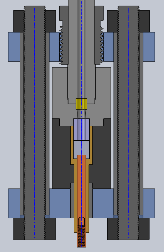
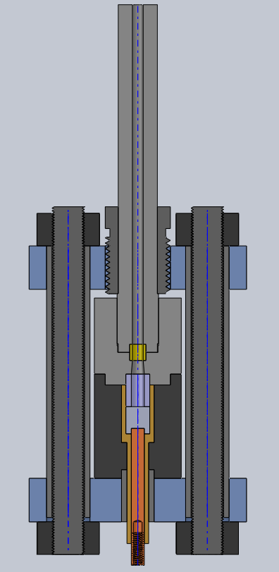
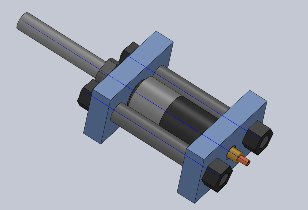
Presented below are some drawings of the new design. Most of the functions and materials should be self-evident, but feel free to ask if something is unclear. I'd like some other members' opinions on the integrity of the chamber (as regards firing pressure as well as the high voltage difference present) and manufacturing cost of the insulators. Any suggestions to improve either one would be appreciated. Bear in mind that the design failure pressure is currently 200kpsi.
EDIT: fixed drawings
Posted: Thu Feb 09, 2012 1:04 pm
by al-xg
How is it predicted to fail ?
Posted: Thu Feb 09, 2012 1:13 pm
by sharpshooter11000
How are you going to machine the barrel? I would suggest a center drill and reamer.
Posted: Thu Feb 09, 2012 2:06 pm
by DYI
Sharpshooter: center drills are not for starting drilled holes, they are for, as the name suggests, producing a shallow conical hole to accept a live center. After doing the outside of the barrel, the hole will be made as follows:
Start hole with spotting drill, bore to achieve roundness and straightness of the starting hole, drill in 1" increments with extension drill (having flutes on only the last 2" or so), chase 1" behind that one with an all-flute extension drill 1/64" larger, then ream to .250" after the drilling operation. It won't be as straight as could be done with a gun drill or BTA system, but it's the best I can do, and the bore should be very smooth.
al-xg: That's what I'm asking you

The insulator will clearly be extruded out the back a little bit during a normal shot, but prior experience says that this won't be nearly enough to cause gross failure. For failure to happen in that section, the .550" diameter electrode (likely a Cu-W alloy for the final build) would have to be pushed through the 0.500" hole in the rear casing, which will be normalized 4340 steel initially.
Do you see other likely failure modes? Do you think this one is more worrisome than I do?
Posted: Thu Feb 09, 2012 2:06 pm
by mobile chernobyl
Very nice build plan DYI!
Whats the planned effective chamber volume? And by what means are you restraining the projectile before release (it doesn't look as if there is a convenient place for a burst disk style method in there...)?
Also - are you starting with a significant "preignition" pressure? if so how are you injecting the light gas and keeping it in there? one way valve utilizing the folding skirt on the projectile as a check valve? lol
Also also - are you going to use a bridge wire or spark gap? I'm going to assume bridgewire for ease of initiating breakdown at that pressure.
Folding skirt?

Posted: Thu Feb 09, 2012 2:16 pm
by DYI
A modified breech is required for the light gas shots. Happily, this design readily permits extension of the system length, so designing it isn't too difficult. High pressure burst disks are not exceedingly simple to design or machine, but neither is the folding skirt system. I suspect I'll go with burst disks, when I get around to it.
Also, the threads on the external part of the electrode will likely be male threads, not female. Many of the electrodes for WARTL ended up bent, and those dainty internal threads would only complicate things. I'm also going to put together a more flexible power connection, to allow for more recoil without damaging the electrode.
Posted: Thu Feb 09, 2012 3:45 pm
by al-xg
Hehe, I was just wondering if you'd run a basic simulation in CAD, just as a possible indication.
The insulator is the yellow/gold part right around the copper electrode ?
Posted: Thu Feb 09, 2012 7:04 pm
by Fnord
I'm not sure if I'm seeing this right, so correct me as needed.
Made an image since it's such a small detail to try and point out...
Are you going to be using a 'pressure differential/gas dielectric breakdown' trigger? This kinda looks a little like that thing I sketched up in your Al/H2O thread, but I don't think you ever commented on it so I assumed it was a crappy design
Posted: Sat Feb 11, 2012 10:04 pm
by DYI
To answer a few questions which have popped up since I last checked this thread:
MC: I'll be using a bridgewire, when I get to the light gas experiments. I'm going to be building a kind of "medium pressure" test rig for this in the summer running a significantly lower starting pressure in a larger chamber before I get to the full version. Simply building the pump for the high pressure version will be a fairly involved task.
al-xg: Yes, the insulator is the gold coloured part. I am going to run a basic simulation, although due to the nature of the process involved (a transient pressure spike above the yield strength of most of the materials involved) the results will be less accurate than usual.
Fnord: As I mentioned above, arc initiation is via a bridgewire. I liked your idea, but it's way beyond the level I'm working at right now...
Your idea would be a very nice way to approach making one of these things semi-automatic, if one could come up with an insulator which survived the shots..
As regards the lip, what I'm counting on is that the only failure mechanism available is the barrel material squirting out the gap between the breech and the retaining section. I've seen that happen with polycarbonate before, but I'm not quite at the injection molding pressure for normalized 4340 yet

Posted: Sun Feb 12, 2012 1:57 am
by mobile chernobyl
DYI wrote:....
Simply building the pump for the high pressure version will be a fairly involved task....
Booster pump? any planned method to accomplish this? I've been looking into these for a while for my high mix hybrid. The high pressures I can get for bottled gases weren't as easily available as I thought (need some special cert's for some of the 5Ksi stuff) so I need to look into a homemade booster design for reaching 500X...
Posted: Sun Apr 01, 2012 3:16 pm
by DYI
At this point, unless I can find some MUCH more affordable high pressure / low volume pumps, what I'm looking at is probably hand pumping for the short term. The standard displacement for 10000psi hand operated hydraulic pumps appears to be about 2.5cc. Given a 10cc firing chamber which I want to pressurize to 10000psi and starting with a total of 50cc at 2000psi, that's not a whole lot of pump strokes, even accounting for the inevitable extra volume introduced by valving.
With the volumes under consideration, the high pressure hybrid is a more involved project. I'd initially approach that issue the same way as this one, owing to my current lack of knowledge of high pressure sealing solutions (especially for helium and hydrogen), but it may turn out that the booster is a more affordable and/or practical solution.
The only potential modification I'm considering to this design at the moment is making the chamber casing in two sections to allow for a taper at the back of the central electrode (and on the insulator) which should dramatically reduce stress concentration there while reducing possible dielectric breakdown issues involving the sharp edge. The downside of this, apart from a somewhat longer manufacturing process on my side, is increased per-insulator cost. I'll have to request a quote for the insulators before I make my decision on that matter.
Posted: Wed Apr 25, 2012 9:37 pm
by DYI
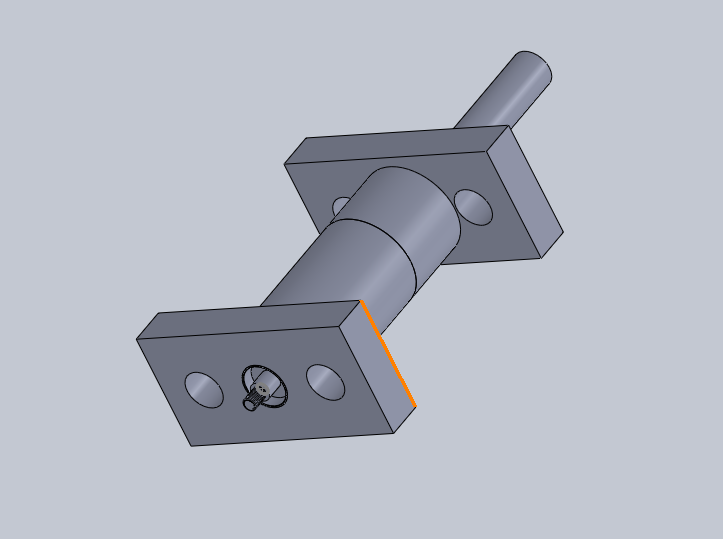
I was a little uneasy with certain features of the old design, and ended up redoing it completely. No fancy colours on these new pictures, but I don't have a great abundance of free time at the moment. You should be able to interpret what's what without too much effort.
External:
Full cross section:
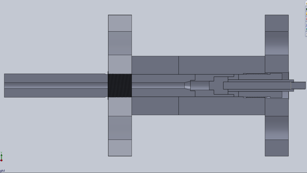
Close up:
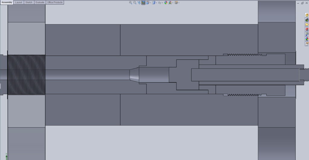
Less single-use parts, should seal just as well and be easier to assemble than the first version. It also lends itself better to various barrel modifications (built-up barrel design, replaceable breech sections) as well as being ready for use as an ELGG with just a bit of modification to the chamber liner and breech. It's also possible to have an internal and external liner, but the initial outlook is that it's not possible with current materials to prevent plastic deformation and severe internal ablation of the liner.
Finally, allow me to direct your attention to what I call the "insulator base", the short, squat section of the insulator which sits directly behind the wide "nose" of the electrode and in front of the steel threaded plug. I think I might be able to make it reusable

The only other possible trouble I can see is the potential for a surface arc from the electrode nose along the insulator base into the outer casing. I'm confident I can prevent this with a simple surface treatment, but I'll be testing this component before I buy the materials to build the rest of the launcher. Can you guys spot anything else?
For the keeners among you: yes, I'm aware that the thread pitch on the barrel is not standard. It's for illustration purposes. I'll probably use 36TPI or so on the actual build.
Posted: Wed Apr 25, 2012 10:51 pm
by warhead052
May I ask what sort of mix you would be using? I assume this would be along the lines of a hybrid, but more powerful... I don't see many failure points at all, the only ones that pop to mind are, 1. the threads themselves but it looks like there are enough to hold, and 2. the area in the chamber, it looks like it is just compressed together by the rods on the outside.
Posted: Wed Apr 25, 2012 11:06 pm
by DYI
1. Yes, the threads are long enough. They're actually significantly longer than they need to be, and there are a few other points likely to fail first.
2. Yes, it is. I didn't include those due to time constraints. They are, however, going to be 1" grade B7 all thread and will be more than sufficient for what they're holding, even in the case of total seal failure.
This gun is designed to allow several different propellant compositions - the aluminum/water reaction I was using last summer, as well as inert condensed propellants like water, and, later on, high pressure light gases. I'm not considering any hybrid mixes currently.
I also feel the need to note that the endplate on the back of the launcher appears to be preventing the threaded plug from being turned. This will be remedied, as the actual reloading cycle requires turning the plug to finish clamping the internals together.
Posted: Wed Apr 25, 2012 11:19 pm
by warhead052
Ok, what sort of pressures are you planning on using? I don't see any failure points now that you have told me that.