Difference between revisions of "Launcher configuration"
m |
|||
| Line 13: | Line 13: | ||
* "multiple tanks and Ts" | * "multiple tanks and Ts" | ||
| − | Like the setup used on the megah-launcher. However, the multiple bends results in lower flow. The [[GGDT]] typicaly doesn't show much improvment from the increased chamber volume. | + | Like the setup used on the [http://www.spudtech.com/images/products/mega-II-ov2.jpg megah-launcher]. However, the multiple bends results in lower flow. The [[GGDT]] typicaly doesn't show much improvment from the increased chamber volume. |
Revision as of 23:18, 18 October 2005
Chamber-Barrel position
The possibilities are limmetless, but these are the most common ways to position the chamber and barrel:
- "linear"
The barrel is directly infront of, and pointing in the same direction as, the chamber. It's slightly cheaper than the over/under configuration, but only by the cost of 2 90* elbows.
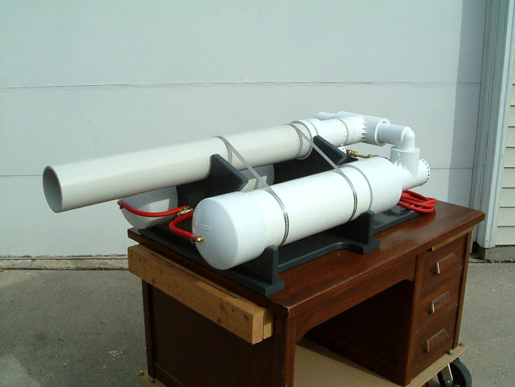
- "over/under"
The barrel is turned 180* (using 2 90* elbows, typicaly) so that it points in the oposite direction of the chamber, and is directly over it. This makes the total launcher length shorter, although the 90* bends will slightly reduce flow. Barrel suports are recomended to re-enforce the launcher, and keep the barrel steady.
- "co-axial"
The barrel is placed inside the chamber. This is made possible by modding the reducing bushing, allowing the pipe to be glued in it backwards. This makes a rather nice looking launcher, and is most commonly used when constructing a diaphram or piston valve, which requires the part near the valve to be co-axial anyway. It can be a pain to vent and mix the combustion products/fuel if you make a co-axial combustion.
- "multiple tanks and Ts"
Like the setup used on the megah-launcher. However, the multiple bends results in lower flow. The GGDT typicaly doesn't show much improvment from the increased chamber volume.