Page 1 of 2
revo semi 2 few questions
Posted: Fri Aug 21, 2009 4:16 pm
by colty-bear
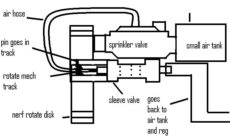
ok im getting parts i almost have parts so i make a sucky diagram of how i think it will work
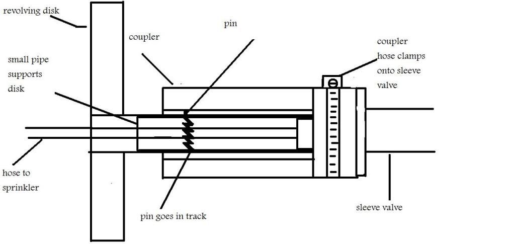
a pin rotates this little track whan you push the slide valve sorward and pull it back
Posted: Fri Aug 21, 2009 4:44 pm
by Hubb
Have you ever considered using a clicky pen for the rotating assembly? With a small launcher like the Revo Semi, it is probably quite possible and it would make the revolver deal go much easier in assembly.
Posted: Fri Aug 21, 2009 5:53 pm
by colty-bear
wow good idea it might be a lil small wouldnt it? one inch and if you look at the first revo does it look like his tank connects to regulator then to 3/4? to me it looks that way cause a 1/2 sleeve valve OD would be pretty close
Posted: Sun Aug 23, 2009 1:16 pm
by colty-bear
sorry for double post but i need to know if it will work so i can start
Posted: Sun Aug 23, 2009 1:22 pm
by Mr.Sandman
How can you cal it a revo semi 2. You didnt make the first one so you have no right calling it the revo semi 2. It should work but im not sure how your rotating mech works.
Posted: Sun Aug 23, 2009 1:53 pm
by colty-bear
ok sorry i wont call it revo semi 2 ill think of a new name but here
Posted: Wed Aug 26, 2009 8:06 am
by Hubb
The biggest problem I have come up with when working with revolvers is the little zigzag portion that actually spins the devise. Without an extreme amount of patients and precision, this is near impossible for the average joe to complete.
In other words, I suggest looking into other methods of rotating the barrels. I have (in my head) some good thoughts on doing this that are a lot easier (and possible for us) to build. I'll put them on paper eventually and share them.
Posted: Wed Aug 26, 2009 2:14 pm
by PVC Arsenal 17
I was doing this, I would consider putting a cylinder perpendicular to the turret so that after each shot, the rod pushes the turret and rotates it a certain amount. It would take some figuring out to get the rotation right, but it could be more simple than machining tracks and whatnot.
Posted: Wed Aug 26, 2009 2:32 pm
by ALIHISGREAT
For the jagged portion have you thought of using a drill bit?
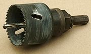
Not sure if it would be viable given the amount of teeth but its worth mentioning.
Posted: Wed Aug 26, 2009 2:47 pm
by Hubb
Even if the jagged rotators was built, it would still need to be aligned. A hole saw would work, but it would only spin the chambers a very small portion.
Good thought though.....
On the note of jagged rotators versus zig-zag rotators, a jagged rotator would probably be easier to build and would most certainly be more durable.
If it helps,
here is a link to a revolver that Boltsniper began (but, unfortunately, never finished).
Posted: Fri Aug 28, 2009 11:37 pm
by colty-bear
the track will be like this and a pin will slide in it
http://www.spudfiles.com/forums/revolver-t6497.html
Posted: Sat Aug 29, 2009 2:52 am
by john bunsenburner
I assume using something as simple as a dremel tool and a rotary cuting bit(Al<sub>2</sub>O<sub>3</sub>) one could make gears for a revolver.
If you plan it out well and use PVC it should be fairly do able.
When using a hole saw one could grind of, lets say, every 2<sub>nd</sub> tip, thus solving the problem Hubb touched apon.
Hmm, This sounds like a fun project to attempt next...Full metal construction though, hmm...
Good luck
Happy spudding!
Posted: Sat Aug 29, 2009 6:26 pm
by colty-bear
what if i made a mech where there is a stop and you pull back and go forward and inside was a twisted spring then after the shots wind it up again?
Posted: Sun Aug 30, 2009 6:07 am
by john bunsenburner
Thats even more complex, stick to the good ol revolver mech thats hard enough.
Posted: Fri Sep 25, 2009 9:08 pm
by iknowmy3tables
NO NO NO NO NO

, if you understand and have the craftsmanship to do it it than it is not to complicated, I'm sorry about resurrecting this topic, but I knew keepitreal, I talked with him in the topics where me and others explained to him many of the basic setup of pneumatic semis, and in the topic were he talked about the rotary cam,
it seams to me that none of you have a dam clue about how a rotary cam works, it's pretty simple, it easier than making a true reliable working revolver based mechanism, keepitreal's creation was suppose to prove to the spudgun community that it is in fact practical to build your own rotary cam.
colty-bear, your design is fine assuming you just sketched a plain zig zag out of laziness and your intended design for the cam grooves looks more like keepitreal's then yes you shold know what your doing and you should ignore these people.
draw out your intended cam design on the pipe very carefully before you cut, send me a message next time you need help and these guys aren't giving you much, I'm not that active anymore but your private message should send me an email alert,and if for some reason I don't respond within 10 days feel free to send me another