Rifling Machine

A place for general potato gun questions and discussions.
User avatar
CS
Moderator
Moderator
Posts: 1837
Joined: Fri Feb 18, 2005 5:32 pm
Location: Southern Utah

Donating Members

Mon Sep 07, 2009 3:37 am

I'm going to build a rifling machine and would like some feed back before I go ahead.

Rifling Design: (PICTURES BELOW)
First off I think the square lands of typical rifles not to be translative of potato launching. The face created by the depth of the land seems to more directly exert shear forces.

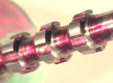
Sketched some designs up. The left section has arc lands with equally sized bits of undisturbed pipe in between. The right section is all cut (broached), with no original interior surfaces left, with a design similar to the ridge line of knuckles.
Image

For example a ganged broach for standard rifling.
Image

Testing:
I'm figuring a range of 360*:30-60" ratio to test. I'm thinking to chronograph and use a spread test (cardboard target) for optimization.

Cutter Design:
The cutter would be of a broach design, incrementally increasing the cutter size to gradually remove the material. For the testing one broach section will be drawn thru at a time to avoid re-alignment of a ganged broach. As different rates of rifling would required individual adjustment of the ganged unit. Therefore the broach would only be ganged once the desired ratio is found.

The cutter design would obviously replicate the contours in the rifling. Additionally on the face of the cutter, 1/16" inward from the edges a 1/8" ball mill would be used to produce a positive rake angle cutter along the edges.
Image
Positive rake chipping
Image


Machine Design:

Linear movement would occur on two 6' sections of angle iron using skate bearings to support a carriage. The pipe will be fixed, having a acme threaded rod driven carriage, and slowly rotating cutting head.
Image

Similar to the article I will use acme threaded rod for tapping, however milling slots lengthwise instead. Then drilling a pilot hole the size of the root diameter.

During testing I'll use steppers, but for a final design the two movements will be geared together and operated by rotating a handwheel connected to the acme threaded rod. Using a hypocycloid reduction gear for the rotation of the cutter.

90:1 Hypocycloid (link
Image

^Video - Youtube
Attachments
Two rifling designs
Two rifling designs
rifledpipe.JPG (10.21 KiB) Viewed 5378 times
Angle iron rail for carriage
angleironrail.JPG (5.04 KiB) Viewed 5378 times
As you see I got stumped on sketchup, but the 1/8" ball mill, 1/16" inward from the edge, creates the cutting edge.
broachsegment.JPG (13.54 KiB) Viewed 5351 times
Rifling machine
Rifling machine
riflingmachine.PNG (14.3 KiB) Viewed 5259 times
Last edited by CS on Tue Sep 08, 2009 10:16 am, edited 3 times in total.
User avatar
twizi
Corporal
Corporal
Posts: 511
Joined: Thu Nov 27, 2008 9:04 pm
Location: up yours

Mon Sep 07, 2009 8:28 am

cool looks good surprised nobody has posted have not seen u in a long time cant wait for a build log
dont play with airsofter with 1000$ gun and play with a 5 dollar pair of glasses
User avatar
jrrdw
Moderator
Moderator
United States of America
Posts: 6572
Joined: Wed Nov 16, 2005 5:11 pm
Location: Maryland
Has thanked: 39 times
Been thanked: 22 times
Contact:

Donating Members

Mon Sep 07, 2009 8:39 am

Looks like a workable design. If it's the modeling of the tool that has you "stumped" contact Dewey-1 he seems to be the best modeler we have.

Otherwise where are you having trouble, I don't notice any mechanical problem in your design.
User avatar
rna_duelers
Staff Sergeant 3
Staff Sergeant 3
Posts: 1739
Joined: Mon Sep 26, 2005 7:07 am
Location: G-land Australia

Tue Sep 08, 2009 4:04 am

Now this has me interested!

So you are going for a push die style of cutting (correct me if I'm wrong) If memory serves correct then this will be a slow process.Have you thought about the pipes OD changing from the machining process,such as "ballooning" of the pipe.
Image
User avatar
CS
Moderator
Moderator
Posts: 1837
Joined: Fri Feb 18, 2005 5:32 pm
Location: Southern Utah

Donating Members

Tue Sep 08, 2009 10:17 am

Actually pulling, slow... it'll be 10TPI so in the test range that is 90-180 seconds per rifling pass. Made a diagram to clarify the overall function of the rifling machine. So with the 2" sch. 80 sleeved around the 1.5" pipe that should help out with ballooning. More importantly the cutter should engage rather then deform and create such a deflection/ ballooning force. IE wedge. Similar to using circular saw and if not enough material is cut it will deflect the blade.

Uploaded the rifling machine diagram: riflingmachine.PNG btw it is shown just prior to the start of the rifling process.
Post Reply