Make a Y connection to a PC sound board input.
On one side of the Y input a homemade LED chrono.
On the other side a microphone half the distance to the target.
Audacity will show 4 blips if the sound travel time to the mic is longer than the projectile reaching the 2nd LED.
A really nice speed measuring experiment that I would like to see.
A suggestion: Drill 2 holes through a 2 foot length of 1" PVC exactly 1 foot apart. Mount the LED/photo transistor pairs in the holes.
Place the PVC centered and lined up to the axis of your cannon barrel and shoot through it.
BoyntonStu
A 1:2 Chronograph experiment for LED/Audio
-
jimmy101

- Sergeant Major 2


- Posts: 3210
- Joined: Wed Mar 28, 2007 9:48 am
- Location: Greenwood, Indiana
- Has thanked: 6 times
- Been thanked: 18 times
- Contact:
If you use the typical stereo input to the soundcard then you can use a stereo Y and use both stereo channels, one for the optical and one for the audio. For a MIC input the three detectors can probably be wired in parallel, so you might need a Y or just a breakout board.boyntonstu wrote:Make a Y connection to a PC sound board input.
On one side of the Y input a homemade LED chrono.
On the other side a microphone half the distance to the target.
I would think the setup would always give four blips, unless you just managed to get the MIC at the perfect distance so the sound and 2nd photodetector got their signals at the same time. Even then, the two peaks are probably significantly different.boyntonstu wrote:Audacity will show 4 blips if the sound travel time to the mic is longer than the projectile reaching the 2nd LED.
A really nice speed measuring experiment that I would like to see.
What exactly are you trying to learn with this experiment? Verifying and/or calibrating the optical chrony with the sound signal?
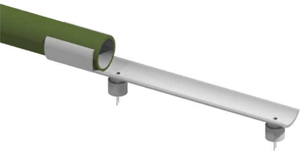
Works great for ammo up to perhaps 1/2"D. Personally though, I don't see a lot of need for the LEDs unless you plan on shooting in the dark. If you mount the detector on the muzzle then you don't have to worry so much about the alignment between the detector and the round's line of flight. The holder for the transistors can be made from a chopped up piece of the same pipe the barrel is made out of. The barrel is green, the transistor holder gray and the holder just clips onto the barrel. The holder is automatically offset from the ammos line of flight by one pipe wall thickness.A suggestion: Drill 2 holes through a 2 foot length of 1" PVC exactly 1 foot apart. Mount the LED/photo transistor pairs in the holes.
Place the PVC centered and lined up to the axis of your cannon barrel and shoot through it.

-
boyntonstu

- Sergeant

- Posts: 1039
- Joined: Sun Jun 28, 2009 8:59 am
Perfect!
K.I.S.S.
A mic to verify and to calibrate.
BoyntonStu
K.I.S.S.
A mic to verify and to calibrate.
BoyntonStu