
Google sketchup can be downloaded here.
Google sketchup is a fairly small (in size), easy to use modelling program. So..I'm writing a tutorial on how to use it, similar to my paint tutorial a while ago.
When you run sketchup you'll be greeted with this screen:

Choose a template that sutis you. I use product design and woodworking, and seen as I speak in metric I use mm. You can use whatever template or increments that suit you, but I reccomend the product design ones. (If you wanted to, you could use one that includes the model of a person for size comparison of a whole cannon).
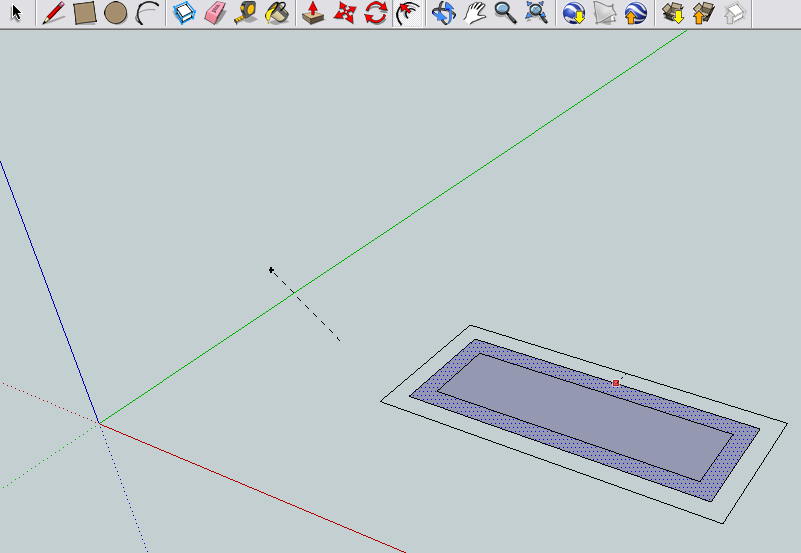
Line/draw tool:
This tool is as simple as it gets. Click to start a line, move your mouse, click again to finish the line. If the box is complete (no breaks) it will become shaded. The line color will change (eg. blue, red green) depending on what axis the line is parralel to. This is useful to keep your drawings on the right dimension and to keep them square (parralel) and accurate. For some angles the line can also turn purple (parralel to edge), which can be used to align two angled lines.
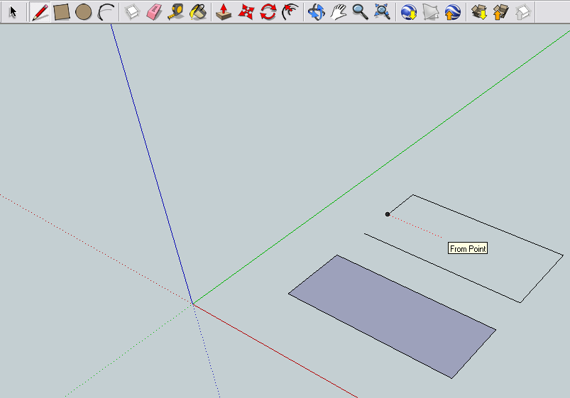
If you start a line, then (while still having the line rubber-banding) mouse over a point (eg endpoints, midpoints), then move the line back to line up with an axis a light dotted line can appear, reading "from point". This is useful to end a line in the right place (to line up with the end of another line, so a straight edge can be drawn). The color of the dotted line will also change depending what axis it is aligned with.
Instead of clicking in two random places, you can draw lines to the exact length you need. Start the line (first click), and aim it in the exact direction you want (often aligned with one of the axis). Then just type the distance wanted (this is where your template comes in..if you're using mm this measurement will be in mm) and press enter (return). A line will be drawn in the direction you had aligned and the distance you entered. The number you are typing (dynamic) will appear in the bottom corner.
Rectangle, circle and arc tools:
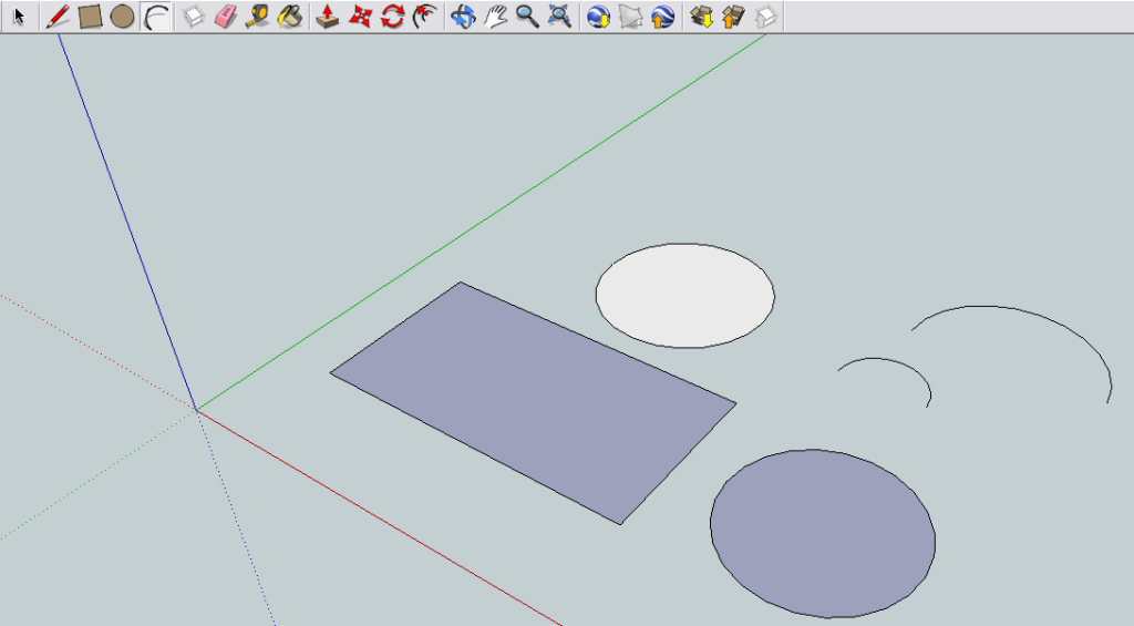
These tools are quite useful for building shapes quickly, particularly the circle and arc tools. These work in a similar way to the pencil tool, just a few clicks. The rectangle begins from one corner and is extended out. The circle begins from the centrepoint, and the arc has two points selected (outer points) then the arc extension length selected.
The rectangle dimensions can be altered precisely by typing in the distances separated by commas (eg. 10,35- L x W). The circle startpoint can be selected, then the radius can be entered in the same way. To accurately draw arcs, select the startpoint, enter the distance and direction as you would for a line, hit enter, then select the extension (which can also be typed in).
A dashed line can appear within the rectangle (to represent a square or golden section- aka two 3, 4, 5 triangles inside the rectangle) and the circle radius can be aligned upon an axis. The arc tool can also 'snap' to a semicircle automatically (mouse it to roughly a semi circle, and it will snap to it).
Component, Eraser, measure and paintbucket tools:
Not so vital tools. Make component is useful when you are working with a large number of objects and would like to be able to move and edit each part separately. Highlight the parts you wish to make a component, select "make component" from the toolbar and enter details such as a name and description, alignment etc.
Eraser tool is self explanitory. Select it, click (and drag if you wish) to destroy lines (that you probably didn't want destroyed). Edit -> Undo if you delete something you didn't want to.
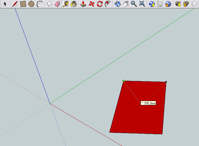
The measure (tape measure) tool is usable by you to gather the dimensions between points. Click to start, measure the line then click again to stop measuring. Also aligns with the axis'. Useful to determine how far to push something (eg. to make a hole through a shape) or similar.
The paintbucket tool is mainly cosmetic. Click it, select a material (fake looking, at that) or color, and paint surfaces as you wish. Helpful to differentiate between different objects.
Push & pull tool:
Used to pull and drag faces to create 3d objects. Select it, mouse over the face (it will show a blue selection shading). Move your mouse to change the elevation, click again to finalize.
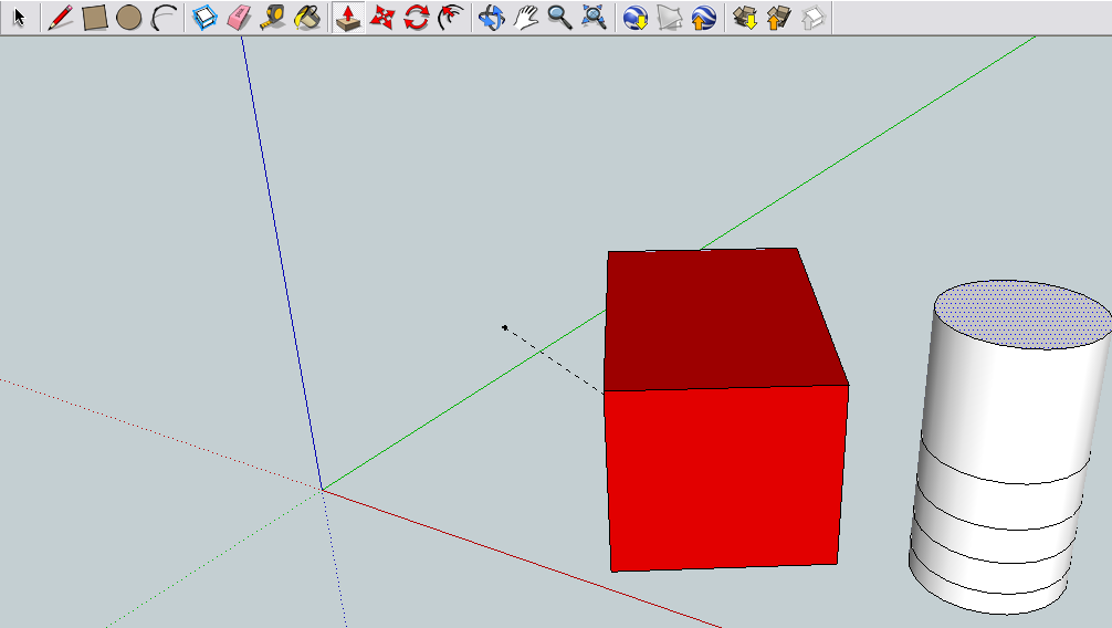
Pressing ctrl then clicking will create a new layer upon the other (think of pulling something as a continuous cake, and ctrl + click as a layered one). The main use for this is to delete parts of a cylinder (or similar) after it has been drawn, eg. making minigun barrel supports.
The push pull tool can also be used precisely by selecting the direction of push/pull then entering the height/depth to push to then pressing enter/return, in a similar way to other functions.
The push/pull tool and also be used to push shapes out of objects to create a hole/path through them. It refuses to push/pull curved surfaces, but there is a workaround here if you're keen.
Move & Rotate tools:
Need little explanation of what they do. The move tool can be used to drag faces (mouse over the face, click + drag). To drag entire shapes (or components) select them using the select tool (the mouse pointer) then use the move tool to drag them. A line is shown from the original drag point to help show direction (and return it if you change your mind).
The rotate tool can be a little finicky. If you have problems using it, try this:
1. Select a face. Pretend this face has a small axle protruding into it (from the protractor center).
2. Select a basepoint. If something is facing south, then 180 degrees (south) would be a good point).
2. Rotate the part. This is expressed in degrees from the basepoint and can be manually entered by entering the degrees (eg. 258) then pressing enter.
The part will rotate about the center point of the protactor (the first click you made). If you have problems with it, just practice rotating something simple until you get the hang of it.
A note on the select tool:
I nearly left this out. Click to select a line. Drag to select a shape. Click to deselect. Ctrl + click to add more lines to a selection.
However, remember this:
1. Dragging from top left to bottom right only selects lines that are completely covered by selection.
2. Dragging from bottom right to top left selects any lines touched by the selection.
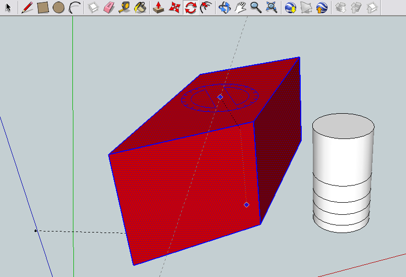
Offset tool:
This copies the object selected (select a face, the blue selection shading will occur before clicking) and scales it proportionally in or out. Useful for creating the exact same shape..but bigger, layers, coatings, walls etc.
This can also be used precisely by selection direction (aka- bigger, smaller, in, out) then entering the distance as usual and hitting enter. The distance entered is the length between the edge of the selected face and the edge of the new shape.
Orbit, pan, zoom, move + zoom:
These are just your move tools. THESE DON'T MOVE THE PART, JUST THE CAMERA! Orbit rolls (orbits, lol) your camera around the mouse click. Pan slides the camera across the mouse click, and zoom moves the camera closer and further away. I usually just use the mouse wheel to zoom in and out (it will zoom in centered basically around your pointer).
Publishing/finishing your drawing:
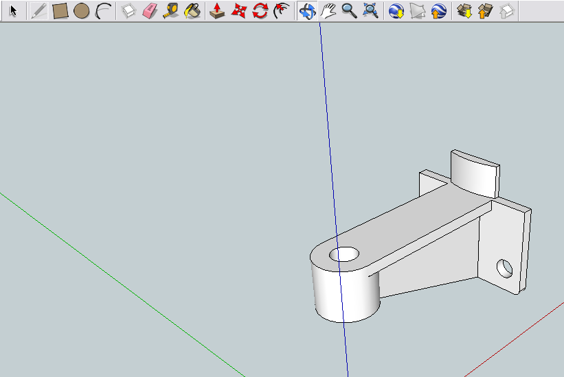
Let's pretend you've finished your model, and you want to hand it to a worker/drafter/machine operator/spudgun fund supplier, but it has to be printed out. You can obviously manipulate views to get orthagonal views of the shape, and take screenshots of any angle you need. But if it's printed, they lose all the digital dimensions that were accosiated with the model. So, those dimensions need to be represented somehow.
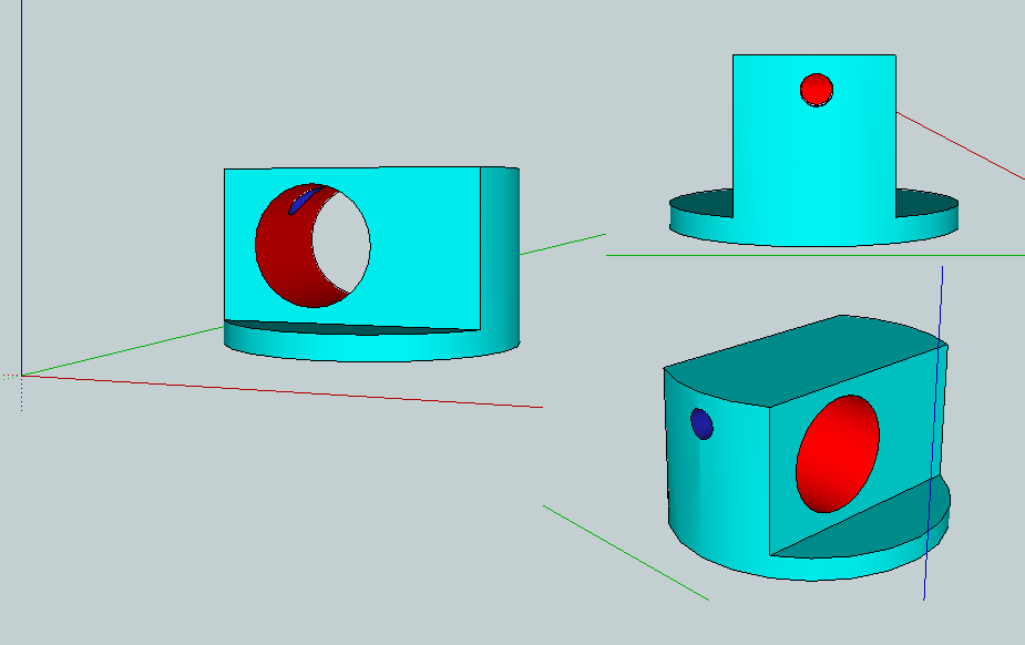
So, for example we have this bracket that needs machining (the dimensions are random, yes):
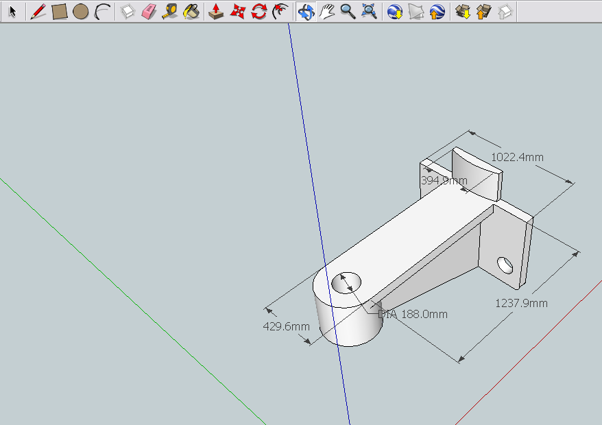
So to begin with..we'll add dimensions to it. Under the "tools" menu click "dimensions" (a tick will come up next to it in the menu). Now, click on two points (eg. endpoint, midpoint) and a measurement arrow will appear. Drag it away from your piece (or offset it the distance you want, the usual way) and you get a nice arrow with the distance on it. Repeat as required.
So..after a few dimensions have been added we get this:
Under the same menu you can add text, 3d text etc.
For the time being, that's almost it. If anyone wants more added, like layers etc. Then feel free to yell out, but this should be a good start for anyone new to this.