Page 2 of 7
Posted: Wed Aug 27, 2008 6:38 am
by Brian the brain
The 1/4" port means you can't use ammo over .50 anyway.
I'd say up to 10 mm is best.
Full auto by it's very nature means you are gonna need a lot of gas to run it.
The quest was to get a cycling valve in order to get lower ROF, yet still have a lot of power.
The plus is, this design doesn't waste pilot volume to do so.
Posted: Wed Aug 27, 2008 5:16 pm
by FishBoy
that is frickin sweet.
can't wait to see it in action (and the damage)
Posted: Wed Aug 27, 2008 5:31 pm
by Sticky_Tape
JSR is gonna epoxy the hell out of you btb well when he gets back from spain.
Posted: Wed Aug 27, 2008 6:59 pm
by daberno123
OK so if I've got this right then this is the order of steps...
1. chamber is filled
2. chamber pressure increases to the set pressure of the spring holding the snap valve closed
3. air hits larger piston surface area, "snapping" valve open.
4. When the snap valve is opened, the o-ringed rod attached to the piston slides forward into the chamber.
5. Air fills the space behind the snap valve (where the spring is), closing the valve quickly enough that most of the pressure stays in the chamber.
6. Cycle restarts
Did I miss anything? I stared at the diagram for awhile and that's what I got out of it.
Can't wait to see a prototype

Posted: Wed Aug 27, 2008 7:52 pm
by Lentamentalisk
I think not...
trigger is pulled
Chamber is filled
reaches firing pressure, so the big piston setup slides forward
inlet is cut off, and the pressure hits the larger surface area
piston "snaps" open
chamber is dumped of pressure, to the level that the large surface will hold against the spring
the system closes, and the inlet is unblocked
chamber is filled again
now the problem that I see with your drawing, is that when the system has just fired once, there is still air trapped inbetween the chamber and the barrel, acting on the "extra" "snap" area of the piston.
Clide solves this by making that "extra" area vent directly to the barrel. You could solve this by just changing the location of your porting to barrel to always be open to the "extra" area of the piston.
I understand that this slows down the opening of the snap a little, but I don't think it will work with out that.
I really like clide's method, because it seems much more compact, though I would go with a real spring rather than an air spring, as that could be leaked into, or could leak, and mess things up
edit: also, do you have a loading mech in mind? or any links to loading mechs to use with this. I am not sure as to whether there would be sufficient piston movement to hook that up to the opening and closing mechs of some breach system.
Posted: Wed Aug 27, 2008 8:34 pm
by Lentamentalisk
Ok, double post...
here is my idea, basically the same as clide's, but with a real spring (not really drawn...)
the advantages are that:
a) it could be made out of standard fittings
b) it uses a metal spring, that is fully accessible, in an area that holds no pressure, so it is easily adjustable
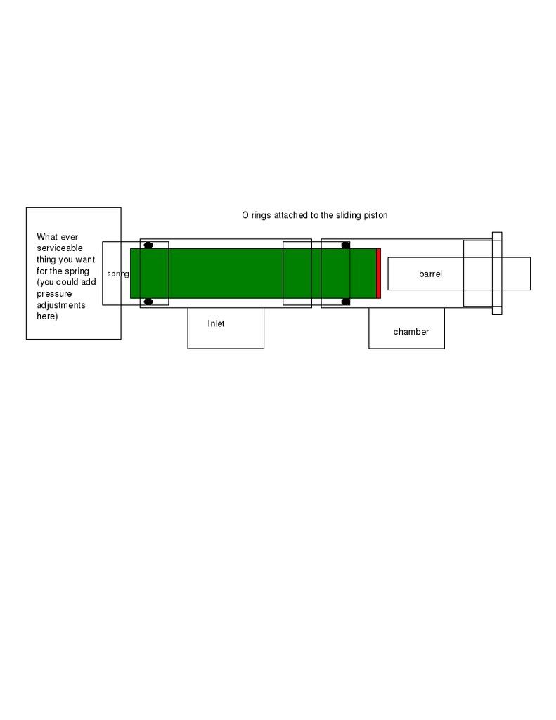
What do you think?
edit: sorry about that big image, cant really cut it down at the moment
Posted: Wed Aug 27, 2008 11:42 pm
by Hailfire753
Wow, behold the future of pneumatics. BTB, you giving out autographs?
Seriously, the drawing and explanation were easy to understand, and it does not look that hard to make with the right tools. Awesome worthy.
Posted: Wed Aug 27, 2008 11:57 pm
by Lentamentalisk
Granted, they said the same about the original repeater that showed up here, but this is so much easier, and can be made out of standard pipe fittings. REALLY good job, I must say.
Posted: Thu Aug 28, 2008 11:59 am
by Brian the brain
The original repeater was...a repeater.As in , recock manually for multiple -single- shots
This is a design for full auto.
Cycle is like this ( a little different from what Lenta said)
1.Chamber is filled
2.Pressure reaches critical point and small area starts releasing gas.
3.This pressure hits the larger surface area and the force on the piston
( already at point of " failing" ) suddenly increases. while springforce remains equal.
4.Piston snaps back, pushes blockrod to stop gasflow.Surface area of the blockrod exposed to the pressure is no longer exposed to incoming air.
5.Pressure drops,and so does the force on the blockrod, so the force trying to close the piston decreases, allowing even longer exhaust, untill piston returns and closes.
1.Airflow is restored and cycle repeats.
Today I though up another way of blocking the airflow, by using the valve in a regulator.It will no longer regulate pressure after that, but will function as a shut-off valve .In order to make that work, I'll have to machine a block of aluminium.
This will become acilinder wich houses a piston that will push the pinvalve inside ( with help of spring) the reg.
The piston replaces the diaphram.
The assembly will be placed between the fill valve and chamber.
Air can leak past the piston in a similar way seen in piston valves.
When the pressure drops, the piston will travel away from the pinvalve, releasing the pin wich cuts off airflow.
Because of both the amount of travel , and the small blowby, the piston will stay off the pinvalve long enough for the chamber pressure to drop significantly, allowing the snapvalve to reset.
The pinvalve-piston resets and pushes open the pinvalve, cycle repeats.
It sounds like the same could be done with a poppet valve, but a reg valve is not hindered by pressure differencial.
If the first idea ( topic) fails, this is another option to explore.
I'll do another draw-up
Posted: Thu Aug 28, 2008 2:00 pm
by jackssmirkingrevenge
A tad complex for my liking, and too many o-rings... but hey, if it works
video?
Posted: Thu Aug 28, 2008 2:46 pm
by Antonio
jackssmirkingrevenge wrote:A tad complex for my liking, and too many o-rings... but hey, if it works
I agree. It would be so nice to c this work though. As you have the resources (I think it was ur brothers laithe/milling machine) go for it:)
Just a oveall question> Do you guys think it is possible to make a HP (not co2) automatic gun that doesnt have a regulator nor a solenoid or handopening valve (like on brians latest creation). I mean no offence to brian I mean u make awesome stuff. But as long as the trigger pull is in relation to dwell time/cycle rate I dont think it is automatic as your finger/hand is putting in significant energy into the system"". Ofcourse a mechanical trigger also needs input of energy. To my oppinion this is less, what is your trigger pull"" experience on your gun brian? I was thinkin about it last time> that jacks design with the popoff valve only works in certain pressure range (too low and the poppoff wont open) I experience the same with my hammer valve based designs. What are your thoughts?
Posted: Thu Aug 28, 2008 4:18 pm
by iknowmy3tables
nice job reminds me of my design
http://www.spudfiles.com/forums/full-au ... 13928.html
it's probably easier to make, I like how it turns of the input when firing, a good plus over mine since you probably want to use a high flow input for performance, you could probably ignore the big o-ring and go with friction like a lot of simple piston valve do
Posted: Fri Aug 29, 2008 4:16 pm
by Brian the brain
To answer all of your questions:
I too think it is hard to get right, so I tried something else with the snapvalve first, wich I will adress below.
O-rings are a pain in the ass, so the less, the better.
Trigger pull is just right.Not too soft to cause accidental firings, not hard to press while entire mag empties.
So, now the good news:
I have achieved perfect full auto today, combining my snapvalve and modded QEV, wich fills chamberside.Wich eliminates the problem that the ordinare QEv and pop-off causes, namely exhausting incoming air along with the pilot.very wastefull.
Perfect pop/pop/pop/pop and virtually NO airloss.
I muffled the barrel with a bottle and some paper towels and the exhaust is pretty darn quiet.The barrel however pops noticably when not muffled, telling me the system is quite efficient.
The exhaust valve has a tiny ajustment valve at its out/port wich I turned down untilll it stopped working.Then gave it a turn back and voilá:
Nearly no wasted pilot volume and perfect firing main valve.
Low flow meant fast shots, more flow means slower ROF, but more powerfull shots.This is because high incoming flow from the chamberside makes the QEV stay open longer.
This too can be controlled by installing a flowvalve between the incoming air and the chamber.
I have recieved an airgun barrel, .177" for only the postal costs ( great guy!!!) and I shall use this on this system.
I'll be lathing a blowforward bolt this sunday.
The new version of the Deartray should fire a hell of a lot more powerfull.
I accidently hit my thumb with a bb and it is swolen up like balloon.
Got a bloody welt on it, once again reminding me of how dangerous a hobby like this can be to an idiot like me!
This was at 3 bar.
It hurt like hell and it could have stopped a bankrobber.
I'll set the system to about 21 bar when it's completed, so go figure.
It should embed every shot into wood..pop-pop-pop-pop!1
Muhahaha

Posted: Fri Aug 29, 2008 8:23 pm
by Lentamentalisk
can you give us a new diagram of your setup? I am having a little trouble figuring it out. I understood the original snap valve, but I don't get how you used it with the QEV/popoff setup.
Posted: Sat Aug 30, 2008 7:58 am
by Brian the brain
The snapvalve takes the place of a normal pop/off.
On the pilot side of a QEV.
By the snapvalve I mean the piston and housing part on the left of the drawing.
Without the blockrod thingy.
The QEV´s diaphram has a tiny equalisation hole punched into it and a soft spring behind it to return it to closed position.This makes it
" modded"
That's it.
Basically just the qev with pop-off, but in a better way.
It works so well, I'm not even gonna try anything else.