

I must be misunderstaning something.
Why would you need a remote interlock but not a remote fire?
Are you referring to a wireless remote rather than a wired remote control or being able to use either or?
Are you trying to do both Arm and Fire or just Fire remotely?
I read the first post and it says Fire.
For now just ignore the charging circuit.
Launching circuit - cool and simple?
-
Davidvaini
- Sergeant 4

- Posts: 1315
- Joined: Tue May 29, 2007 8:58 pm
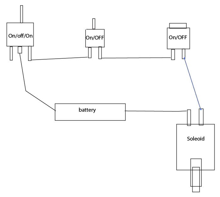
I would have a 1 switch that would work as a safety, and then another button switch that would be the firing button. So both switches would have to be on their "On" state in order to fire the gun. There is also a 3rd "optional" switch in the middle. The optional switch could be a jumper (so no actual switch) or an on/off switch. The reason for this other switch is to make it so that if I want to take my launcher and put it on the side of the road, I can use my remote keychain switch - to fire the device.
The remote keychain device acts just like an on off switch, it is just wireless.
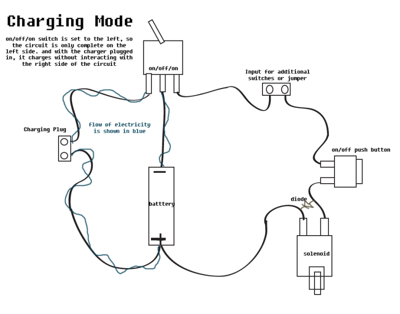
The whole reason for this external port is so that my design can be modular and i can plugin different "accessories" into it. for example, I could have a really long cord with a switch on the end so I can fire my launcher while I am behind something at a safe distance, or I could do the remote trigger, or I could hookup a PIR sensor (that triggers a relay).. etc another accessory would be the charger. This way I can charge the battery inside the launcher without having to take it out, all i have to do is plugin the charger and flip the on/off/on switch to the left.
I think the idea is a good one, just gotta figure out how to do it.
The remote keychain device acts just like an on off switch, it is just wireless.
The whole reason for this external port is so that my design can be modular and i can plugin different "accessories" into it. for example, I could have a really long cord with a switch on the end so I can fire my launcher while I am behind something at a safe distance, or I could do the remote trigger, or I could hookup a PIR sensor (that triggers a relay).. etc another accessory would be the charger. This way I can charge the battery inside the launcher without having to take it out, all i have to do is plugin the charger and flip the on/off/on switch to the left.
I think the idea is a good one, just gotta figure out how to do it.
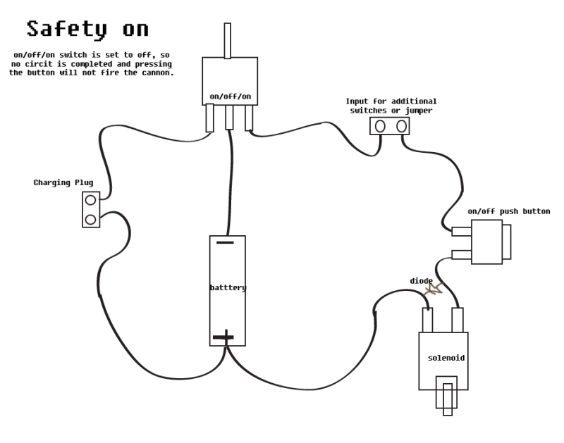
This is what I envision to get the remote fire or local fire mode you need.
Note that the Safety Jumper Interlock is actually used to "program" a Safe Mode and a Remote Fire Mode.
You need to to use a separate charge connector.
Note that the Safety Jumper Interlock is actually used to "program" a Safe Mode and a Remote Fire Mode.
You need to to use a separate charge connector.
- Attachments
-
-
Davidvaini
- Sergeant 4
- Posts: 1315
- Joined: Tue May 29, 2007 8:58 pm
So i wont be able to have one plugin for the charger and the remote trigger? I have to have one plugin each?
I figure there should be a way to do it if I use a on/off/on switch..
and I guess I am kinda confused what you mean by inter-lock.
I wouldnt use the jumper for safety at all, id just have the on/off/on switch turned off to be the "safety".. because if it was in it's off state the circuit wouldnt be complete and therefore you wouldnt be able to fire it...
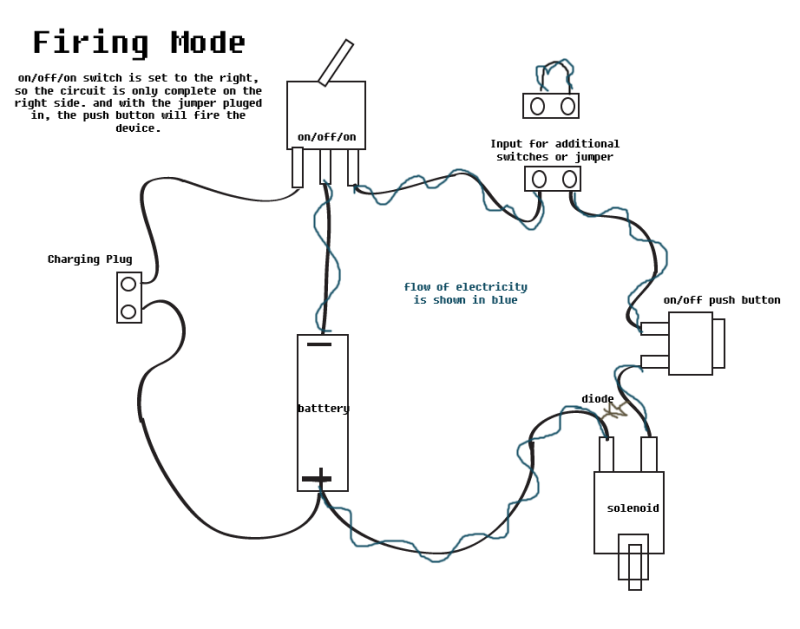
the on/off/on, the plugin switch, and the fire button would all be in series, and all 3 would have to be on in order to complete the circuit and fire the solenoid. and by all 3 being on I mean that the on/off/on switch is fliped to the right. If it was flipped to the left, then the loop would only go battery, pluged in, and on/off/on switch.
I figure there should be a way to do it if I use a on/off/on switch..
and I guess I am kinda confused what you mean by inter-lock.
I wouldnt use the jumper for safety at all, id just have the on/off/on switch turned off to be the "safety".. because if it was in it's off state the circuit wouldnt be complete and therefore you wouldnt be able to fire it...
the on/off/on, the plugin switch, and the fire button would all be in series, and all 3 would have to be on in order to complete the circuit and fire the solenoid. and by all 3 being on I mean that the on/off/on switch is fliped to the right. If it was flipped to the left, then the loop would only go battery, pluged in, and on/off/on switch.
-
Davidvaini
- Sergeant 4
- Posts: 1315
- Joined: Tue May 29, 2007 8:58 pm
see that switch in the middle that would be removable and you can replace it with a jumper to complete the circuit. You could also replace it with the two ends from a battery charger. IF and only if you plugin the charger, would you have the on/off/on switch turned to the left to complete the circuit for only the battery, the plugin, ad the battery.
Does that make more sense?
Before I go any further and waste my time:
The right most switch is that a momentary push for Fire?
So what is the middle switch function?
What you going to use for batteries and also what are using to charge them?
What are the specs or part/model number on that solenoid valve?
The right most switch is that a momentary push for Fire?
So what is the middle switch function?
What you going to use for batteries and also what are using to charge them?
What are the specs or part/model number on that solenoid valve?
- Attachments
-
-
Davidvaini
- Sergeant 4
- Posts: 1315
- Joined: Tue May 29, 2007 8:58 pm
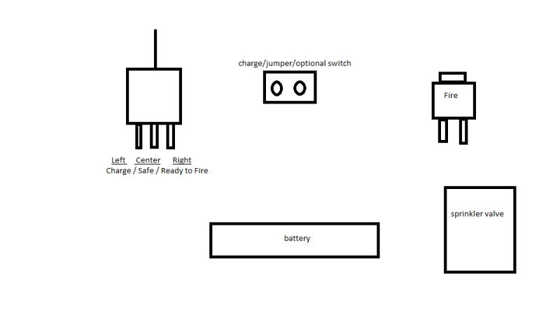
the right most switch is the momentary push for fire, the middle switch is the optional switch as I stated above. It is where the plugin would be to allow a remote switch, or a jumper, etc... I just put a switch there since that is pretty much what is going to be there anyway.
the battery is a 8.4v nicad, 1000mAh DC battery, and the solenoid is for a sprinkler valve, I have used the sprinkler valve with this battery before without any problems, the only major concern is how to wire this to allow that middle "switch" to be replaced with the wall charge used to charge the battery. the wall charger outputs DC at 400mA
I dont need anything over complicated or over engineered, or anything too complicated, I just want that middle switch to be modular. AS in I want to be able to replace that middle switch with the positive and negative ends of my charger and flip the on/off/on switch to the left to use the charger, flp it to th emiddle to turn it off, and flip it to the right to avoid the whole charging and just make sure i can fire the cannon.
maybe this helps:
I have a circuit that will do what you want.
The Safe/Arm switch is DPDT that is not center off.
The "dual" switch allows total isolation between Charge and Arm circuitry.
D1 and R-Charge are used for the charging circuit.
The value of R-Charge is a 100 Ohm 1/2 Watt 5% and allows approximatly a current 50 mA if using a 12 VDC charger.
This will be about as simple as possible to do all your modes of operation.
Maybe Tech can review this to be sure I did not make any blatant errors.
Edit: Removed Jumper J2 in Normal mode, not needed. Schematic updated to reflect this change.
- Attachments
-
Last edited by dewey-1 on Sat May 28, 2011 7:53 pm, edited 1 time in total.
-
Davidvaini
- Sergeant 4
- Posts: 1315
- Joined: Tue May 29, 2007 8:58 pm
sweet sounds good, yeah that is a good idea thinking about it that way. Thanks for all your help and your patience. I was having a difficult time explaining what exactly I wanted it to do.
While you were creating that one, I created my own alternative circuit, It doesnt have 1 plugin for both charging and accessories, but it cover everything else.
Now I think I will probably go with your circuit, but I am curious, would this circuit work as well? I am starting to pick up on electronics a little bit more, and I am curious to see if I finally made a circuit that would work. Or if I am misunderstanding something fundamental...
oh and the the charger is made for the battery and It doesn't have any problems charging at the 400mAh rate - and the charger will shutoff when it has finished charging.
Your circuit will not have remote fire capability.
You need the remote fire switches in parallel like I have shown.
If you use my circuit you will have the functions you wanted.
The DPDT switch does not need a center off.
It has only an "Arm Mode" and "Safe/Charge Mode".
You need the remote fire switches in parallel like I have shown.
If you use my circuit you will have the functions you wanted.
The DPDT switch does not need a center off.
It has only an "Arm Mode" and "Safe/Charge Mode".
-
Davidvaini
- Sergeant 4
- Posts: 1315
- Joined: Tue May 29, 2007 8:58 pm
ah I finally completely understand it now. okay cool, so like in my picture above, if I plugged in the remote switch, I would have to have the rmeote switch turned on and the fire button pressed at the same time for it to work. while parallel is one or the other need to be turned on. Right?


I don't mean to hijack this thread or anything, but here is the console I am using on my pneumatic cannon. I am using a key switch safety to actuate a relay for the firing and hydraulic circuits (top left switch is firing, top right is UP-off-DOWN control, bottom left is lighted momentary push button trigger).
[youtube][/youtube]
[youtube][/youtube]
ROLL TIDE ROLL
-
Davidvaini
- Sergeant 4
- Posts: 1315
- Joined: Tue May 29, 2007 8:58 pm
yeah kind of a hijack, but I have to say that sounded kinda like the shark coming in JAWS.. dooo do doooo do doooo do lol but yeah very cool.Jimmy K wrote:I don't mean to hijack this thread or anything, but here is the console I am using on my pneumatic cannon. I am using a key switch safety to actuate a relay for the firing and hydraulic circuits (top left switch is firing, top right is UP-off-DOWN control, bottom left is lighted momentary push button trigger).
anyway back on topic....
David now you understand what I was getting at all along.
With the parallel setup you could have multiple remote "fire"switches like trip wire switches.
With the parallel setup you could have multiple remote "fire"switches like trip wire switches.
-
Davidvaini
- Sergeant 4
- Posts: 1315
- Joined: Tue May 29, 2007 8:58 pm
Thank you soooooooo much!
okay, I am going to try to draw my circuit but in parallel to see if I understand the concept. (I am one of those learners who learns by trying and doing.. if that makes sense) But yeah, cant wait to try your circuit out.
okay, I am going to try to draw my circuit but in parallel to see if I understand the concept. (I am one of those learners who learns by trying and doing.. if that makes sense) But yeah, cant wait to try your circuit out.