Page 1 of 2
Electronics Help
Posted: Tue Jan 18, 2011 3:19 am
by Davidvaini
Hey guys, I am working on a project with the Arduino.
The Arduino has pins that output ~5v at ~40mA. I want to be able to control a motor that requires quite a bit more amperage and voltage. (12-24v, 15amp max) I want to keep the realm of PWM (Pulse Width Modulation) possible and I heard a N-Channel Mosfet (Field Effect Transistor) is the way to go. I found a mosfet that can easily handle the higher amperage that I need as well as the voltage. I have it on good authority from several people that a relay would not work for the PWM requirements. And since the mosfet with a heatsink would have no problem with the power requirements, I figured this would be a good way to go. (also no clickity clack )
With some help of others (such as sgort) as I am still a beginner with electronics, I came up with this picture/ physical diagram of the circuit.
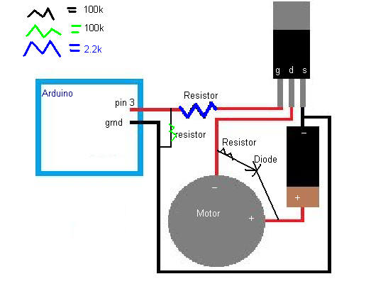
Now I am starting to understand things a little bit with this project and I think I understand the reasoning behind the resistors, and the diode, I just want to make sure that you guys believe this is wired up the correct way.
The mosfet's 3 pins are labeled G, D, S for Gate, Drain, and Source.
Pin 3 on the arduino supports pwm output.
Posted: Tue Jan 18, 2011 7:18 am
by Technician1002
1 eliminate the resistor in series with the diode across the motor.
Hmm Gif not working.. I'll link to the page instead. See circuit 8 on this page.
http://www.picotech.com/applications/pwm_drivers/
Another good page showing the circuit from the data pin of the Arduino and the MOSFET is on this page.
http://www.electronics-tutorials.ws/tra ... ran_7.html
Posted: Tue Jan 18, 2011 8:46 am
by dewey-1
I would highly recommend the use of an opto isolator between the Arduino output and the MOSFET motor driver.
This is to prevent direct noise feedback to the Arduino via the output pin or the ground pin(s). This is perhaps the most important idea to allow for a successful project with out all the troubleshooting of noise induced problems. There are direct noise problems and RF induced problems.
Using the opto isolator will also protect the Arduino from catastrophic failure of the MOSFET. (example: motor supply voltage on the Arduino pin via the gate lead if MOSFET shorts gate to drain.)
Posted: Tue Jan 18, 2011 11:08 am
by Technician1002
Optical isolation can provide lots of circuit protection. It can mask noise sources from ground loops, ground wire inductance, mutual inductive coupling and other hard to eliminate sources of glitches. It is highly recommended if you have no experiance designing the grounds for elimination of all coupling problems.
Opto isolation is the standard industry practice for both the MIDI musical insturment interface and the DMX512 stage lighting dimmer interface.
Due to non linearaties in the opto isolators, it is seldom used for analog audio. They do work well for digital signals and PWM control.
In commercial applications such as a recording studio or radio station, isolated grounds and balanced signal lines are installed just to eliminate noise from the currents in the grounds from inducing noise into signal lines.
Edit, for the typical use in a MIDI interface the diagram is on this page.
http://pinouts.ru/Home/pc2midicable_pinout.shtml
There is not an Opto Isolator in the TX line because it drives the input Opto Isolator inside the instrument. The Instrument then drives the Opto Isolator in the interface diagram shown for optical isolation between the Instrument in both directions.
Posted: Tue Jan 18, 2011 1:26 pm
by POLAND_SPUD
so what about this IC that I posted in PVC Asenal's thread ->
http://www.components.omron.com/compone ... 1_1210.pdf ?
It is an opto-isolator and it can handle up to 60V at 500mA... so you don't need a mosfet for most stuff
yeah I know I know
(12-24v, 15amp max)
but you can use that IC to power most stuff directly... let's face it - you'll find some use for that extra channel

Posted: Tue Jan 18, 2011 1:30 pm
by PVC Arsenal 17
POLAND_SPUD wrote:so what about this IC that I posted in PVC Asenal's thread ->
http://www.components.omron.com/compone ... 1_1210.pdf ?
It is an opto-isolator and it can handle up to 60V at 500mA... so you don't need a mosfet for most stuff
yeah I know I know
(12-24v, 15amp max)
but you can use that IC to power most stuff directly... let's face it - you'll find some use for that extra channel
Wow I must have missed your link. The second output channel would be extremely useful to me. I'd still probably need a MOSFET to drive at least the motor. Not sure about the solenoid but I'm sure it's more than 500mA.
Posted: Tue Jan 18, 2011 2:31 pm
by Davidvaini
yeah my needs are not met with something that can only handle 500mA... I need something rated for atleast 25amp to be on the safe side. continuous power draw is quite high in my case.
thanks for the tip about the opto isolator, So just to make sure, put it between pin3 output and the gate of the transistor correct?
and why remove the resistor that is with the diode? what would be some possible reasons you could think of having it there?
I've never used an opto isolater, nor do I know what to look for in one or how to hook it up..
Posted: Tue Jan 18, 2011 2:38 pm
by PVC Arsenal 17
You don't need a resistor with the flyback diode. What matters is that the diode blocks the voltage spike across the motor.
Look at the internal schematic for optoisolator ICs to see how they work. Think of it like a transitor with an LED and a photoresistor at the base/gate. When a signal is applied, the transistor turns on like usual, except the coupling of the LED and photoresistor prevents stray signals from going
back to the device applying the signal (Arduino). Here's
another one available on a breakout board and corrected for the inversion that occurs within optoisolators. But note it's rated for much less current (50mA). Still good for protecting the Arduino.
Posted: Tue Jan 18, 2011 3:31 pm
by POLAND_SPUD
Not sure about the solenoid but I'm sure it's more than 500mA
and not an expert but I am pretty sure that 500mA at 24V would be more than adequate for most valves
ohh I found a link ->
http://www.boschrexroth.com/pneumatics- ... ID=p256494
Posted: Tue Jan 18, 2011 4:33 pm
by Davidvaini
Its not just going on valves and thus needs to be able to handle the higher amperage.
Posted: Tue Jan 18, 2011 4:40 pm
by PVC Arsenal 17
It's still a good idea to use one in conjunction with the MOSFET as dewey and Tech said. And I find it pretty cool that both of us are doing nearly the same thing at the same time and have made equal amounts of progress.

Posted: Tue Jan 18, 2011 4:52 pm
by irisher
I am pretty sure that 500mA at 24V would be more than adequate for most valves
I think that depends mostly on the type of valve. A sprinkler valve's solenoid can be opened with a 9 volt but my 1/4" 3-way requires 1 amp at 24 volts to open effectively.
Posted: Tue Jan 18, 2011 5:01 pm
by dewey-1
Digi-Key is a good supplier for those living in WI, MN, or upper mid-central states.
Here is a 60V 2.5A SSR.
They also have the lower current ratings.
If you read the spec sheets and applications info you can learn a lot.
http://search.digikey.com/scripts/DkSea ... e=Z2442-ND
Posted: Tue Jan 18, 2011 5:33 pm
by Technician1002
Nice find Dewey-1. The device has a relatively slow turn on time of 1-1.5 ms which limits it's uses in PWM. PWM would have to be well down in the audible range.
Posted: Tue Jan 18, 2011 5:34 pm
by POLAND_SPUD
I think that depends mostly on the type of valve. A sprinkler valve's solenoid can be opened with a 9 volt but my 1/4" 3-way requires 1 amp at 24 volts to open effectively.
Yeah, it seems so. Something tells me that direct acting valves might require more power...
Anyway... I hope you know that you can use PWM to reduce power consumption, right ? once the solenoid opens the valve it requires less power to keep it in open position...
so for the first, let say, 30ms the solenoid receives full 24V at 500mA (I suspect they can handle more as long as the impulse is fairly short) and then you reduce power consumption by 50% with PWM