
The Arduino has pins that output ~5v at ~40mA. I want to be able to control a motor that requires quite a bit more amperage and voltage. (12-24v, 15amp max) I want to keep the realm of PWM (Pulse Width Modulation) possible and I heard a N-Channel Mosfet (Field Effect Transistor) is the way to go. I found a mosfet that can easily handle the higher amperage that I need as well as the voltage. I have it on good authority from several people that a relay would not work for the PWM requirements. And since the mosfet with a heatsink would have no problem with the power requirements, I figured this would be a good way to go. (also no clickity clack )
With some help of others (such as sgort) as I am still a beginner with electronics, I came up with this picture/ physical diagram of the circuit.
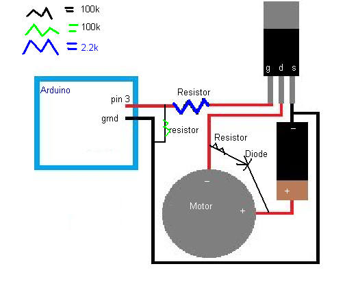
Now I am starting to understand things a little bit with this project and I think I understand the reasoning behind the resistors, and the diode, I just want to make sure that you guys believe this is wired up the correct way.
The mosfet's 3 pins are labeled G, D, S for Gate, Drain, and Source.
Pin 3 on the arduino supports pwm output.