I've been a bit bored lately, and started playing around with high voltage, so I figured I'd go ahead and compile a paper on all the possible ways I can think up of to use a camera flash to generate the high-voltage needed to ignite combustible mixtures. I'm probably just gonna get four cheapo flash cameras to work with, all the same brand and model, and get to work.
What I want to do is describe and detail the following processes:
1.) Capacitor Power: Using the most obvious and well documented aspect of the disposable camera to create high voltage.
a.) Straight spark gap. See if there is any way to create a spark gap small enough, with conventional and available tooling, to be powered by simply switching the capacitor with a mechanical or solid-state device.
b.) Transformer. Detail and describe all the possible ways to run and ignition coil off the capacitor. This covers all the ideas on the Wiki already, and also I might look into ways to convert the single voltage spike from the capacitor into a multitude of spikes over a longer time period, probably combining something like a diode and an inductor.
2.) Charging Circuit Wizardry: Here I'm going to detail the ways of using the charging circuit for the capacitor to run an ignition coil or other transformer to produce high voltage.
First task is going to be completely mapping out and coming up with a circuit diagram for the camera's triggering and charging circuits. There are probably some "generic" ones on the Web, but I'm going to go ahead and study the circuit board of one of the camera's I've got and come up with a circuit diagram, along with component values, (resistor values, capacitor values, transformer winding ratios, part numbers, etc.), to accurately judge the output of all of the methods I try out.
Finally, the second task is to put it all together into the document. My plan is to detail the process of each way of creating the output with step by step instructions and pictures, for people who aren't experienced in electronics, (like me), and then the simple paragraph description of what the resultant circuit is doing, so more advanced people can just say "Ah..." and go build it without even looking.
If you have other ideas of how to use a camera's circuitry, (i.e. specifics on how to use the charging circuit, other ways of switching the capacitor or dampening the spike into oscillations), post them here. And, no, I'm not asking how to do it. I already know the charging circuit produces square-wave low-voltage and square-wave high voltage, so that makes it much simpler to run an ignition coil off of.
Thanks for reading! Expect much more of it once I finish this paper in a few weeks or so...
101 Ways (Not Really) To Use a Camera Flash...


I've already done that one, heres the extract from the UKSGC where I posted my micro charging circuit:markfh11q wrote:First task is going to be completely mapping out and coming up with a circuit diagram for the camera's triggering and charging circuits.
Hotwired wrote: Ok. I'll sketch it up for you.
I'll try and stuff the actual circuit in a scanner in a sec and see how it comes out.
Heres my original sketch-up of the circuit.
Very important that you remember that the connections are shown looking down at the TOP of the transformer and transistor.
This is it. It does NOT include the LED bit that lights up when its charged.
It shows a little capacitor where you would stuff the big fat capacitors and an extra diode. You only need one diode really.
Had to flatten it to the scanner with a cushion so it would all come into focus
I know there are two different types of basic transistor out there but all the transistors I've snaffled from flash circuits have done as they were told and work with the legs arranged like that. You can't tell but the domed part of the transistor is facing you in the scanned circuit so you know which way round to fix it.
This is what it should be like.
The two yellow dots are where you would connect an LED (snaffled from a flash camera) and a 100 ohm resistor in SERIES. Make sure the LED is the right way round. Look inside it and the leg that turns into a fat cup thing inside the bulb should be connected to the negative wire.
The LED will light up when
[a] theres nothing being charged (you've disconnected the capacitor maybe)
the capacitor is charged over about 200v
It goes off when the capacitor is being charged.


There are issues such as the leg position and types of transformer varying between camera models. A generalisation is that if the transformer is small and only has five legs then it'll work.
-
jimmy101

- Sergeant Major 2


- Posts: 3210
- Joined: Wed Mar 28, 2007 9:48 am
- Location: Greenwood, Indiana
- Has thanked: 6 times
- Been thanked: 18 times
- Contact:
I was recently thinking about the same thing, ways to get a spark from a photoflash board. There are lots;
1. The built in high voltage trigger of the flash board (5~10 KV).
2. Replacing the small low ESR trigger cap with a larger one (perhaps even a photocap) to boost the current in the trigger.
2. Three wire setup (like http://www.angelfire.com/80s/sixmhz/camera.html).
3. Dumping the photocap through;
_ 3a Automotive ignition coil
_ 3b Home-rolled transformer
_ 3c 12V Transformer wired backwards
Probably several other ways as well.
Some schematics for various disposable cameras;
http://members.misty.com/don/kflashf.gif
http://members.misty.com/don/kflashe.gif
http://members.misty.com/don/kflashm.gif
http://members.misty.com/don/fflash1.gif

-
mark.f

- Sergeant Major 4


- Posts: 3640
- Joined: Sat May 06, 2006 11:18 am
- Location: The Big Steezy
- Has thanked: 58 times
- Been thanked: 62 times
- Contact:
@Jimmy: I've actually played quite a bit with the 3-electrode method. The remnants of these experiments litter my closet as we speak. My main problems were that the gap needed to be pretty small, and it needed adjusting after only a firing or two, because black oxide would coat the electrodes. I tried using brass as well, but it eroded enough after 10-20 shots. Also, I read around 2-3 kV on those trigger transformers.
It looks like there's not much info on running some sort of autotransformer off the pulsed current through the charging circuit. That's one of the things I'll be doing.
@Hotwire, thanks for the diagrams, but I'll have to make my own with the camera's I plan to test on. They're cheaper ones which are pretty much regional.
I'll have to wait till tomorrow, though. I left the camera's at work, along with my jacket and some rulers.
-
jimmy101
- Sergeant Major 2
- Posts: 3210
- Joined: Wed Mar 28, 2007 9:48 am
- Location: Greenwood, Indiana
- Has thanked: 6 times
- Been thanked: 18 times
- Contact:
Mark, you are probably right, the trigger transformer probably runs at a couple KV, though they are generally described as "10KV" transformers.
I wonder what would happen if the storage cap was replaced with the "10KV" trigger transformer?
I've also fiddled around with the three-wire setup. Got the same result you did, it'll work for a few shots then need tweaking. It is pretty impressive when if does work though, giving a pretty respectable bang when the spark fires.
Nothing.jimmy101 wrote:I wonder what would happen if the storage cap was replaced with the "10KV" trigger transformer?
-
jimmy101
- Sergeant Major 2
- Posts: 3210
- Joined: Wed Mar 28, 2007 9:48 am
- Location: Greenwood, Indiana
- Has thanked: 6 times
- Been thanked: 18 times
- Contact:
The diode is between the main step-up transformer and the storage cap, without it the cap won't charge since the voltage from the step-up transformer is AC. For example;markfh11q wrote:IIRC, there's a diode somewhere after the cap to smooth out the current, so removing that and installing the transformer there might work.
You would probably want to leave the diode in place.
-
jimmy101
- Sergeant Major 2
- Posts: 3210
- Joined: Wed Mar 28, 2007 9:48 am
- Location: Greenwood, Indiana
- Has thanked: 6 times
- Been thanked: 18 times
- Contact:
Have you tried it?Hotwired wrote:Nothing.jimmy101 wrote:I wonder what would happen if the storage cap was replaced with the "10KV" trigger transformer?
Yes.jimmy101 wrote:Have you tried it?Hotwired wrote:Nothing.jimmy101 wrote:I wonder what would happen if the storage cap was replaced with the "10KV" trigger transformer?
The AC voltage being produced is not half the input voltage to the cap as might be expected, it's actually a lot lower unless my FLUKE multimeter is lying, which I doubt.
The transformer producing the high voltage pulse is meant for a high voltage DC pulse not AC.
-
jimmy101
- Sergeant Major 2
- Posts: 3210
- Joined: Wed Mar 28, 2007 9:48 am
- Location: Greenwood, Indiana
- Has thanked: 6 times
- Been thanked: 18 times
- Contact:
Bummer.Hotwired wrote:Yes.jimmy101 wrote: Have you tried it?
The AC voltage being produced is not half the input voltage to the cap as might be expected, it's actually a lot lower unless my FLUKE multimeter is lying, which I doubt.
The transformer producing the high voltage pulse is meant for a high voltage DC pulse not AC.
How did you measure the output of the main transformer with a volt meter? IIRC, the output is a moderate frequency (500Hz ~ couple KHz) at very low duty cycle, probably less than 1%. None of my digital voltmeters will properly measure that kind of AC voltage.
Looking at the schematics for various disposable flash boards, it looks like the output of the charging circuit should be ~300V when it is feeding a high impedance load. Indeed, the output has to be 300V if that is what the ultimate charge voltage of the cap is. I don't see voltage doubler circuits (or tripplers or ...) in the schematics of disposable flashes so the "300V" part of the circuit must be producing 300V relative to the circuit ground. (Actually, I believe many of these boards produce -300V relative to the negative terminal of the AA battery.)
With the diode on the output of the "300V" part of the circuit the output is pulsed DC. (D1 in the schematic below)
The power for the "10KV" trigger transformer is supplied (or dumped into, depending on the details of the circuit) by a fairly small cap with very low ESR (equivalent series resistance). So, the trigger coil is operating with a very small energy source, not the photocap.
In the circuit below, the power for the trigger transformer is supplied by the 0.047uF cap, not the 200uF photocap.
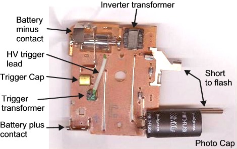
Here is a photo of a typical photoflash circuit from a disposable camera. The trigger cap is labelled. As you can see it is not a standard capacitor type.
I have a Fluke T5-1000 voltage, continuity and current tester which is good to 1KV AC/DC and 100amps.jimmy101 wrote: How did you measure the output of the main transformer with a volt meter? IIRC, the output is a moderate frequency (500Hz ~ couple KHz) at very low duty cycle, probably less than 1%. None of my digital voltmeters will properly measure that kind of AC voltage.
Incidentally I'm certain they bung in any old cap that roughly fits the bill (or more likely the price). I've opened up about 60 cameras and in identical models the caps can be different.
-
jimmy101
- Sergeant Major 2
- Posts: 3210
- Joined: Wed Mar 28, 2007 9:48 am
- Location: Greenwood, Indiana
- Has thanked: 6 times
- Been thanked: 18 times
- Contact:
No they don't "bung in any old cap". Look closely at all your boards, the cap for the trigger is not a standard cap. They are typically in the range of tens of nF, a range where "any old cap" would be a disk cap, which cost a couple cents for hundreds of'm. The photo boards have very specialized caps. That is why the look different on the various boards you've looked at, they are very non-standard.Hotwired wrote:I have a Fluke T5-1000 voltage, continuity and current tester which is good to 1KV AC/DC and 100amps.
Incidentally I'm certain they bung in any old cap that roughly fits the bill (or more likely the price). I've opened up about 60 cameras and in identical models the caps can be different.
The charging circuit of the flash boards generates ~300V spikes. When the photocap is uncharged it's impedance is too low and it pulls down the voltage from the transformer. As the photocap charges it's impedance goes up and the charging circuit's voltage rises to ~300V. The only way to charge a cap to 300V is to supply it with 300V.
I kind of doubt your Fluke meter will accurately read the output from the 300V circuit (with the photocap removed). AC voltage meters assume a sine wave signal and typically rectify the wave then average the voltage versus time (giving the RMS value of the voltage and not the peak value). This method won't work with a wave form that is non-symmetric or has a low duty cycle.
In addition, to measure the voltage output of a low impedance source you need a very high impedance meter, otherwise the meter itself loads down the source and will read low. Most voltmeters have at least a megaohm of input resistance, but even that is too low to accurately measure the 300V supply (again assuming the photocap is removed). Meters have no problem reading the voltage stored on the photocap since the photocap is high impedance, it is the charging circuit by itself that is very difficult to read. The best way to do it would be with oscilloscope (which will probably also require a voltage divider since many Oscopes won't handle a 300V input).
Sam's Strobe FAQ has a ton of info on flash circuits in general, including the ones salvaged out of disposable cameras.
Thats what you thought was it?
When I said any old cap I meant they can vary by about 30V and various levels of uf. You can take it as a given that I'm not oblivious to various forms of capacitors when I post my own circuits and in this case I was referring to the variations in the large electrolytic cap.
I have measured the circuit I made by stripping down a camera circuit to what I wanted, with both my meter and an oscilloscope with a /100 probe. It's more efficient than you might expect.
You might also not know, and it's certainly not said on sams strobe FAQ that a cap and a diode attached to AC is a voltage doubler. In other words, what the AC comes up as is not what comes out as DC.
I'm going to have to make another circuit to recheck numbers, I made three before. One's been potted in a plastic case filled with wax and only has DC input and output wires, the other two seem to have got crushed and/or lost in the junk piled about my room.
-
jimmy101
- Sergeant Major 2
- Posts: 3210
- Joined: Wed Mar 28, 2007 9:48 am
- Location: Greenwood, Indiana
- Has thanked: 6 times
- Been thanked: 18 times
- Contact:
Clearly you do know something about circuits.Hotwired wrote:
Thats what you thought was it?
When I said any old cap I meant they can vary by about 30V and various levels of uf. You can take it as a given that I'm not oblivious to various forms of capacitors when I post my own circuits and in this case I was referring to the variations in the large electrolytic cap.
I have measured the circuit I made by stripping down a camera circuit to what I wanted, with both my meter and an oscilloscope with a /100 probe. It's more efficient than you might expect.
You might also not know, and it's certainly not said on sams strobe FAQ that a cap and a diode attached to AC is a voltage doubler. In other words, what the AC comes up as is not what comes out as DC.
I'm going to have to make another circuit to recheck numbers, I made three before. One's been potted in a plastic case filled with wax and only has DC input and output wires, the other two seem to have got crushed and/or lost in the junk piled about my room.
Still "bung in any old" hardly describes how the trigger cap is choosen for the circuit. You are right that the voltage and farad rating isn't all that critical, but the ESR is very critical.
As far as I know a single cap and a single diode does not form an AC to DC voltage doubler. With a single cap and a single diode you double the AC voltage but you still have AC and the cap's voltage swings from -AC to +AC (see the attachment "A").
To double AC and get a DC voltage you need at least two caps and two diodes (see the attachment "B"). This is gives a single stage of the standard "voltage doubler" circuit.
I don't see a DC doubler capability in the various schematics for the photoflashes. The peak voltage on the cap is generated by the transformer, not a doubler or similar circuit.
- Attachments
-
- Voltage doubler, AC to DC.
-
- AC voltage doubler
- a.gif (39.27 KiB) Viewed 7259 times