Sat May 01, 2010 12:22 am
*Phew*
That took quite a while.
I wound up making two circuits. Not because I thought two circuits would be nice, but because I fried the first one (more on that later).
Anyways, the board measures about 1.5x2.25", takes any voltage from 12 to 35 volts DC, and produces a pulse of ~370 VDC when the trigger leads are shorted (running at ~12 VDC). SCR works like a charm.
Back to the first circuit. I am using a power supply consisting of two 6V gel-cell batteries wired in series. I was flipping the first circuit over when powered to check something with my multimeter, and the arming switch shorted across the positive battery cable, causing much smoke and alarm. No incidents the second time around, though...
I also have a smaller ignition coil from an ATV which produces slightly lesser results than the big coil, but still plenty for a multipoint ignition.
Thanks to everybody for all the help, although, in the end, a single-shot igniter is the best I can hope from my limited electrical skills. If anybody would like the final circuit diagram I could draw it up (it changed somewhat).
EDIT: agh, I'm going to apply a bead of epoxy or liquid tape at the bottoms of all the wires this morning. I was attempting to get a few untangled and one broke off, requiring me to wait for my soldering gun to reheat, solder one joint, and then wait for it to cool down so I could put it away.
Other than that, though, you'll see this mounted in a cannon sometime in the future. Keep it fresh.
-
Attachments
-
 Viewed 1154 times")
- A boatload of wires, but they all have a purpose. They will be trimmed down when the circuit is mounted in a launcher.
-
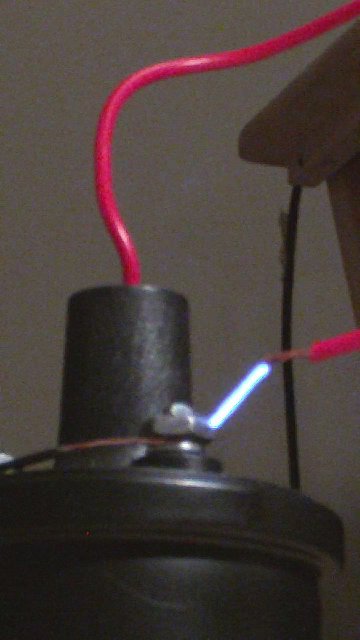
- I was too lazy to measure this gap, though I'm positive it can jump a bit more.
- a0002.jpg (29.64 KiB) Viewed 1417 times