Meaningful discussion outside of the potato gun realm. Projects, theories, current events. Non-productive discussion will be locked.
-
Matt_NZ
- Private 4

- Posts: 65
- Joined: Fri Apr 09, 2010 4:42 am
-
bighead33
- Private 4
- Posts: 98
- Joined: Fri Feb 19, 2010 2:24 pm
- Location: Stonemountain, Ga
Sat Aug 14, 2010 11:47 pm
it would be easier to tell you if i had a circuit diagram but just off the top of my head it might be the capacitors charging or that IC but it's hard to tell.[/img]
-
Matt_NZ
- Private 4
- Posts: 65
- Joined: Fri Apr 09, 2010 4:42 am
Sun Aug 15, 2010 12:27 am
bighead33 wrote:it would be easier to tell you if i had a circuit diagram but just off the top of my head it might be the capacitors charging or that IC but it's hard to tell.[/img]
Sorry, Can't do anything about the circuit diagram. Would it help if i said the time varies before the compressor turns on (2.30-3min).
-
jackssmirkingrevenge
- Five Star General

- Posts: 26216
- Joined: Thu Mar 15, 2007 11:28 pm
- Has thanked: 576 times
- Been thanked: 347 times
Sun Aug 15, 2010 12:34 am
I know bugger all about electronics, but from where I'm standing it looks like you can just take the red and white wires and wire them directly into the plug.
Awaiting some expert advice on how horribly wrong I am

hectmarr wrote:You have to make many weapons, because this field is long and short life
-
Matt_NZ
- Private 4
- Posts: 65
- Joined: Fri Apr 09, 2010 4:42 am
Sun Aug 15, 2010 1:49 am
I know bugger all about electronics, but from where I'm standing it looks like you can just take the red and white wires and wire them directly into the plug.
Awaiting some expert advice on how horribly wrong I am
You might be on the right track. My instinct is that the neutral (comp) is switched. Perhaps if i just use the neutral from the fan instead it may work.
-
Crna Legija
- First Sergeant 2

- Posts: 2333
- Joined: Sun Jul 20, 2008 5:14 am
- Location: australia
Sun Aug 15, 2010 4:38 am
Does it still have the thermostat on it, if so you have to cut it off and put your switch there to turn on/off
'' To alcohol... The cause of, and solution to, all of life's problems.”
--Homer Simpson
Add me on ps3: wannafuk, 8/11/11 cant wait
-
Heimo
- Specialist 2


- Posts: 243
- Joined: Sun Oct 25, 2009 3:02 pm
Sun Aug 15, 2010 4:45 am
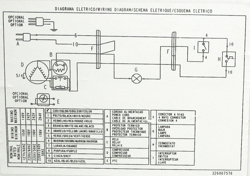
lose the control board and manually wire it up....
here is a basic diagram on how to wire one of these up
The voices in my head may not be real, but they have some good ideas!
-
Matt_NZ
- Private 4
- Posts: 65
- Joined: Fri Apr 09, 2010 4:42 am
Sun Aug 15, 2010 4:00 pm
Heimo wrote:lose the control board and manually wire it up....
here is a basic diagram on how to wire one of these up
Looks good, I have to clarify a few things though.
What is the overload protector? Is there one on the circuit board that I can remove? And same question for the relay basically i.e. Do you see one on the circuit board I can remove?
Also the voltage is 220-240v/50hz and 1.3A current, so is it good to go straight from the wall plug?
-
jimmy101
- Sergeant Major 2


- Posts: 3206
- Joined: Wed Mar 28, 2007 9:48 am
- Location: Greenwood, Indiana
- Has thanked: 6 times
- Been thanked: 18 times
-
Contact:
Sun Aug 15, 2010 4:09 pm
Looks like the circuit board is just a timer, nothing that looks like a power supply or anything like that. So you should be able to just omit the circuit board completely. Also omit the micro switch.
Looks to me like the brown wire from the main switch goes to the red wire of the compressor. The white wire on the compressor goes to the blue wire of the power plug.
Does the compressor label say 240V?
-
Matt_NZ
- Private 4
- Posts: 65
- Joined: Fri Apr 09, 2010 4:42 am
Sun Aug 15, 2010 4:22 pm
jimmy101 wrote:Looks like the circuit board is just a timer, nothing that looks like a power supply or anything like that. So you should be able to just omit the circuit board completely. Also omit the micro switch.
Looks to me like the brown wire from the main switch goes to the red wire of the compressor. The white wire on the compressor goes to the blue wire of the power plug.
Does the compressor label say 240V?
It says 220-240v ~50hz

-
al-xg
- Corporal 2


- Posts: 643
- Joined: Fri Jan 19, 2007 12:29 pm
Sun Aug 15, 2010 4:25 pm
Yep thats it, red, white comming from the relay and earth is all you need.
-
Technician1002
- Captain

- Posts: 5189
- Joined: Sat Apr 04, 2009 11:10 am
Sun Aug 15, 2010 11:23 pm
To make it simple, I modified your wire diagram. The de-ice is a timer to shut off the compressor to defrost it on a regular cycle. Remove the board and tie the wires together as shown. This will connect power directly to the compressor without the timer.
-
Attachments
-
 Viewed 4414 times")
- Removal of the de-ice timer.
-
Matt_NZ
- Private 4
- Posts: 65
- Joined: Fri Apr 09, 2010 4:42 am
Mon Aug 16, 2010 2:14 am
Technician1002 wrote:To make it simple, I modified your wire diagram. The de-ice is a timer to shut off the compressor to defrost it on a regular cycle. Remove the board and tie the wires together as shown. This will connect power directly to the compressor without the timer.
Thanks, Techician. That will come in handy.