I you want to, do a 'How To'
That's a good idea

I started a 3D version of your original drawing
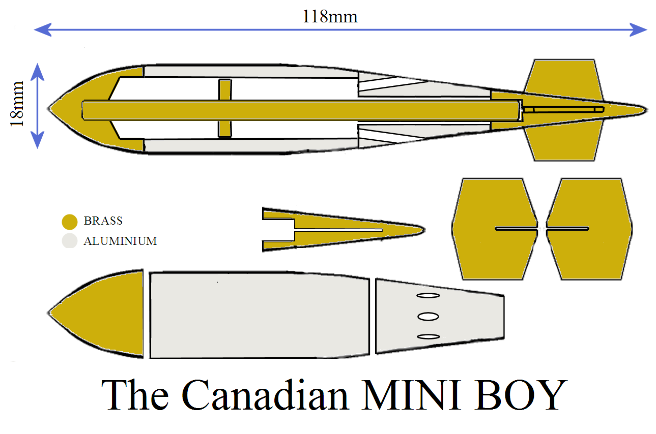
Drawing was not mine really, a copy/paste of the technical drawing JSR posted about the real Tall Boy bomb.
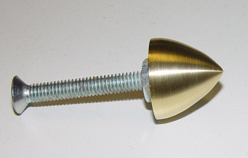
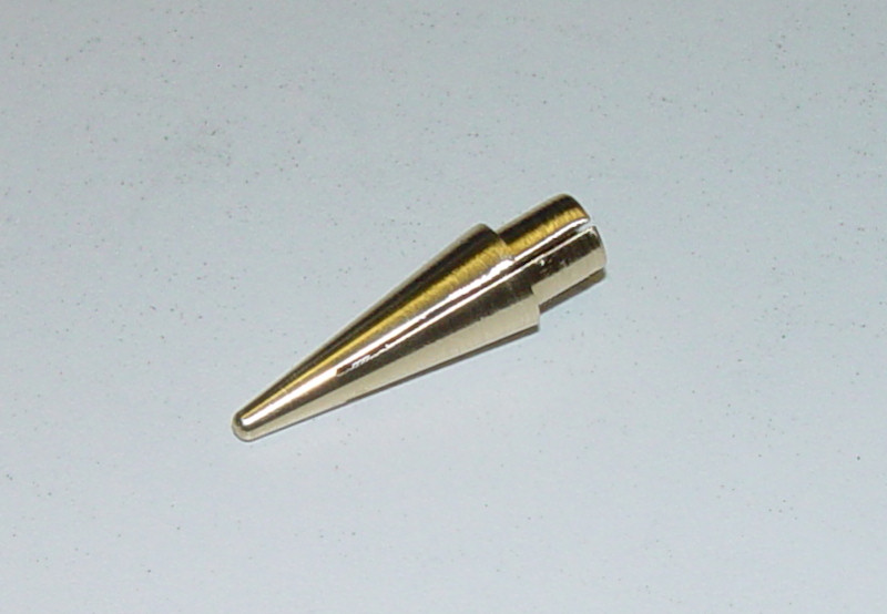
That's interesting! I'll provide weight and exact dimensions of the final missile (I didn't try to do absolutely exact dimensions, more respect and overal shape). So far the diameter is 19mm, I might reduce it when I machine the central part. I'm sure MrCrowley will be interested as he'll be the one that fill the nose and body with weight, as the nose is partially hollow. I made it in brass just to be able to withstand the final hit (hopefully)
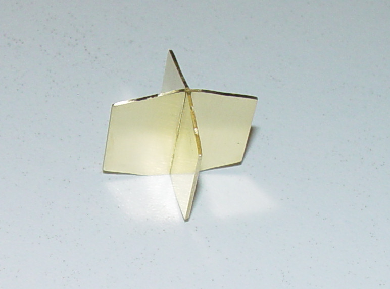
The fins are interesting. I realize you can do shapes not cylindrical on a lathe
I made them with 2 brass plates that interlock together like the drawing... using the mill

I know... I cheated...

I will prepare a How To and post there at the same time so people interested can see the machining process, without clutering this thread with a gazillion pictures

[edit] it's done in
this thread