I'm converting my microscope from halogen to LED and need some help with a few things.
Basics:
*Microscope is from America so it's 110v and I use a 240v step down transformer to power it off my wallsocket.
*Original halogen bulb is 110v 20w
*LED I'm using
*LED driver board
*LED needs to be able to be connected to the microscope dimmer
*LED preferably needs to be connected to the on/off switch
I'm using a 240v (50Hz, 72mA) to 12v DC (500mA) power adapter to currently power the LED. The power adapter doesn't appear to be 240v/110v variable. The LED driver boards maintains the same current regardless of the voltage (within 5v-24v range).
Questions:
Is there a way to do away with the American power cable and just use the 240v-12v DC power adapter to power the dimmer, LED and on/off switch? I'm not sure whether I could connect the dimmer to the 240v side of the power adapter for two reasons: 240v might be too high for the American 110v dimmer and i'm unsure by how much the dimmer changes the voltage and whether it would give me enough 'dim' range for the LED (a range of light intensity from high to low is important for a microscope).
If the above isn't possible, what would be the next best way of getting this all to work?
Photo album can be viewed here:
http://s75.photobucket.com/albums/i290/ ... %20wiring/
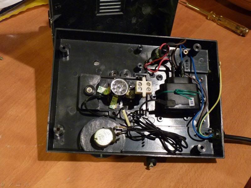
The dimmer is the black round disc with a strip of brown circuit board above it, the on/off switch is to the right of the dimmer. If more photos are required, just ask.
Cheers.
Edit: Someone has done something similar here, they completely removed the circuit board, but they had the advantage of the halogen being 12v. They describe their modification in this PDF magazine.
Halogen to LED conversion help
-
Labtecpower

- Sergeant 3


- Posts: 1297
- Joined: Sat Feb 20, 2010 6:38 am
- Location: Pyongyang
- Has thanked: 5 times
- Been thanked: 13 times
Can you attach a multimeter to the dimmer, and measure the resistance? that way you can calculate what will be the output voltage.
If I understand you, you want 5 volts on the IN of the circuit board?
You can put a resistor on the + of the adaptor, with a resistance of...
R=U/I
R=7/0.5
R=14 Ohm.
With the dimmer you can further regulate the voltage.
If I understand you, you want 5 volts on the IN of the circuit board?
You can put a resistor on the + of the adaptor, with a resistance of...
R=U/I
R=7/0.5
R=14 Ohm.
With the dimmer you can further regulate the voltage.
-
MrCrowley

- Moderator

- Posts: 10078
- Joined: Fri Jun 23, 2006 10:42 pm
- Location: Auckland, New Zealand
- Been thanked: 3 times
Yeah I have a multimeter so I can do that tomorrow morning (in 12 hours).Can you attach a multimeter to the dimmer, and measure the resistance? that way you can calculate what will be the output voltage.

What is the Brand and Model number of the microscope?
Do you have a number for the 110V-20W halogen bulb?
Do you have a number for the 110V-20W halogen bulb?
-
Technician1002

- Captain

- Posts: 5189
- Joined: Sat Apr 04, 2009 11:10 am
The use of the multimeter to measure resistance won't work because the driver board is an active constant current driver, not a series dropping resistor. The requirements are relatively simple. The LED requires ~240-300ma forward current. They don't work properly by simply reducing current. The common way to dim them is to use PWM (pulse width modulation) A 555 timer circuit driving a power transistor such as a MOSFET would work fine to make an adjustable PWM driver. The PWM driver would be placed after the LED driver to limit the current or could be built into a PWM driver. The other option is to buy an LED PWM dimmer/driver that includes the driver as well as the dimmer.
Here is another possibility to replace existing bulb.
I am assuming a dual bayonet style based on your pictures.
You may have to add reflector.
http://www.bulbtown.com/T5_5_36V_130V_W ... /l8039.htm
I am assuming a dual bayonet style based on your pictures.
You may have to add reflector.
http://www.bulbtown.com/T5_5_36V_130V_W ... /l8039.htm
-
Technician1002
- Captain
- Posts: 5189
- Joined: Sat Apr 04, 2009 11:10 am
Here is an off the shelf 300ma dimmable LED driver that will take 240 AC input and provide everything you need to drive your 300ma LED.
http://www.alibaba.com/product-gs/45692 ... river.html
http://www.alibaba.com/product-gs/45692 ... river.html

-
MrCrowley
- Moderator
- Posts: 10078
- Joined: Fri Jun 23, 2006 10:42 pm
- Location: Auckland, New Zealand
- Been thanked: 3 times
It's an Amscope M600A, there wont be any spec sheets with circuit diagram I imagine. No number for the halogen bulb, incandescent microscope bulbs are notoriously difficult to track down when a replacement is needed.dewey-1 wrote:What is the Brand and Model number of the microscope?
Do you have a number for the 110V-20W halogen bulb?
LEDs don't dim by changing the voltage, only current? I do know there are some LED drivers with dimmers available but they usually have buttons on the side of their circuits or metal contacts to dim them. The trouble is implementing that to the microscope dimmer on the side. A full range dimmer is preferred as well, not one that has just three or four dim modes. The link you provided is promising, though I might have trouble locating one near by.The common way to dim them is to use PWM (pulse width modulation) A 555 timer circuit driving a power transistor such as a MOSFET would work fine to make an adjustable PWM driver. The PWM driver would be placed after the LED driver to limit the current or could be built into a PWM driver.
Sorry, what do I PM you for? It would be better if we discuss the problem in this thread and not via PM.pm me, my dad is an electircan
-
Technician1002
- Captain
- Posts: 5189
- Joined: Sat Apr 04, 2009 11:10 am
Many high power LED's change color and drop efficiency if the current is reduced. It has to do with the way they work. The LED is a near UV LED with a phosphor. The ultraviolet is used to make the fluorescent coating glow in white light much like a fluorescent lamp. At low current the LED does not do it's job so the light output drops and the device starts emitting IR instead. Most LED's do not have a broad color spectrum. The white is created by the coating that takes UV and converts it to white.
Changing the duty cycle instead of changing the current is the preferred method of dimming those LEDs.
http://en.wikipedia.org/wiki/Light-emitting_diode
Changing the duty cycle instead of changing the current is the preferred method of dimming those LEDs.
http://en.wikipedia.org/wiki/Light-emitting_diode
-
MrCrowley
- Moderator
- Posts: 10078
- Joined: Fri Jun 23, 2006 10:42 pm
- Location: Auckland, New Zealand
- Been thanked: 3 times
Thanks for the tip, I have to avoid IR because my camera is IR sensitive. The trouble with using PWM and changing the duty cycle is its complexity, cost and difficulty in finding parts. I'm off to JayCar now and hopefully a staff member there will know a thing or two about LEDs.
-
Mr.Tallahassee

- Specialist 3

- Posts: 364
- Joined: Sun Jul 10, 2011 2:35 am
I would use a PWM myself. I've built a few and they're relatively simple. I used mine for an ignition coil driver that pulled decent (and adjustable) arcs.  This is almost exactly what I used. I would tune the circuit to around 1kHz. This unbelievably long link is a java applet I found that seems to work very well. I took the above circuit and modified it to suit driving LEDs. I love this applet and it's definitely worth downloading as well.
This is almost exactly what I used. I would tune the circuit to around 1kHz. This unbelievably long link is a java applet I found that seems to work very well. I took the above circuit and modified it to suit driving LEDs. I love this applet and it's definitely worth downloading as well.There is a mistake in the above schematic.
Pin 3 Q and pin 7 DIS are swapped.
Pin 3 Q and pin 7 DIS are swapped.
-
Mr.Tallahassee
- Specialist 3
- Posts: 364
- Joined: Sun Jul 10, 2011 2:35 am
Actually, it does seem like that but this does work correctly. I was even skeptical(edit:My mind is gone right now  ) myself which why I tested it on the applet. Try it. I have yet to run into any issues with that applet.
Last edited by Mr.Tallahassee on Fri Aug 19, 2011 7:50 pm, edited 1 time in total.