you've got like tons of tutorials.
http://arduino.cc/en/Tutorial/HomePage
Both with codes and wiring (and they comment on this) - damn even the software you use to write programmes for arduino already has a bunch of example programms (also those covered in official tutorials) so you hook things up, upload code and then you can experiment by changing the code - I guess that's the best thing about it.
You've got a language reference page:
http://arduino.cc/en/Reference/HomePage
and if you get stuck and can't figure things out on your own you go to:
http://arduino.cc/forum/
you describe your problem, post the code and they tell you what to do
Get a breadboard for it and some basic components (+some cheap basic sensors, a couple of ULN2004 ICs, maybe one L293D) and you're good to go.
Relay question
-
POLAND_SPUD

- Captain

- Posts: 5402
- Joined: Sat Oct 13, 2007 4:43 pm
- Been thanked: 1 time
Children are the future
unless we stop them now
unless we stop them now
-
MrCrowley

- Moderator

- Posts: 10078
- Joined: Fri Jun 23, 2006 10:42 pm
- Location: Auckland, New Zealand
- Been thanked: 3 times
Thanks for the links POLAND, if I attempt a project that requires Arduino I'll think about learning how to use it.
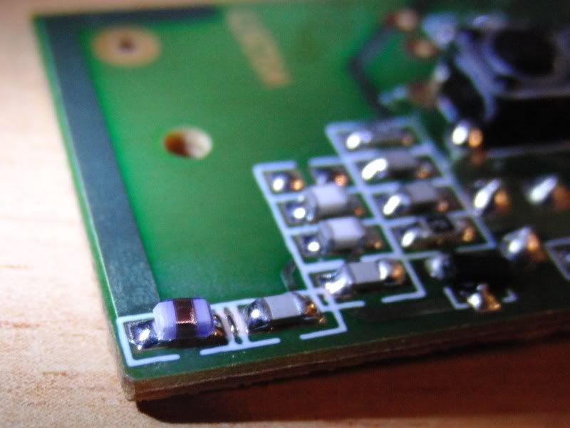
On a different topic, I'm lead to believe the component in the bottom left corner of the board is a capacitor and the copper trail leading above is the antenna of the transmitter? I read that someone suggested cutting the copper antenna line and soldering a coaxial cable to the capacitor with the other end of the coaxial cable wired to a 433.92MHz antenna with an SMA connector. Good plan or...
Edit: Oh and do I need an antenna specifically for the 433.92 frequency? I can't find any at my local electrical store, most operate in the GHz range.
It's like if we knew as much as Dewey about electronics we would have: made robots to drive us to work; breakfast, lunch and dinner would be prepared automatically and sent on conveyor belt to the garage and we would have a remote for everything from the T.V. to the girlfriendjackssmirkingrevenge wrote:I know what you mean, almost every conversation with dewey provokes that feeling
Last edited by MrCrowley on Tue Nov 08, 2011 3:36 am, edited 1 time in total.
-
POLAND_SPUD
- Captain
- Posts: 5402
- Joined: Sat Oct 13, 2007 4:43 pm
- Been thanked: 1 time
I've got my remote for women right in my pantsa remote for everything from the T.V. to the girlfriend
Children are the future
unless we stop them now
unless we stop them now
-
jackssmirkingrevenge

- Five Star General

- Posts: 26216
- Joined: Thu Mar 15, 2007 11:28 pm
- Has thanked: 576 times
- Been thanked: 347 times
POLAND_SPUD wrote:I've got my remote for women right in my pants

hectmarr wrote:You have to make many weapons, because this field is long and short life
-
Technician1002

- Captain
- Posts: 5189
- Joined: Sat Apr 04, 2009 11:10 am
Before modifying an antenna, be aware that using a coax to remote an antenna works best if the circuit is already the nominal impedance of the coax. For example to remote a 50 ohm antenna, 50 ohm coax can be used. In many printed circuit applications the onboard antenna is not 50 ohms and adding the coax will de-tune the transmitter and reduce the range. Do not attempt to modify an antenna unless you are able to retune the radio properly. In the US changing a transmitter antenna of a self contained type accepted radio transmitter is illegal.
-
MrCrowley
- Moderator
- Posts: 10078
- Joined: Fri Jun 23, 2006 10:42 pm
- Location: Auckland, New Zealand
- Been thanked: 3 times
Ah thank you for that, Tech. I had read a guide to making a PCB antenna that went through some steps such as matching the impedance of the components but wasn't sure if I would have to do the same. It looked a bit difficult for me since he had a bunch of equipment to do it but I'll keep searching around for other ways.
-
MrCrowley
- Moderator
- Posts: 10078
- Joined: Fri Jun 23, 2006 10:42 pm
- Location: Auckland, New Zealand
- Been thanked: 3 times
Update:
Everything is pretty much done and in working order. The remote part of the ignition stops working once I put the box together so I need to figure out what's shorting and then I'm done. Doesn't help #1 contact on the relay broke off, need to superglue some plastic between the contacts to make sure they're not shorting if the wires get moved around a bit.
Thanks for all the help.
Edit: Oh is there anyway to change the length of time a signal is sent through the relay? 3 seconds is quite a long time when a quick spark is all that is needed, drain on batteries too (hence the two 9V's wired in parallel).
-
mark.f

- Sergeant Major 4


- Posts: 3640
- Joined: Sat May 06, 2006 11:18 am
- Location: The Big Steezy
- Has thanked: 58 times
- Been thanked: 62 times
- Contact:
Just a little niggle. A 2.4 GHz system would be much better from a safety standpoint, but I think you'll be fine with proper safety practices in the first place...Interference from CBs,
Taxis or remote control toys
operating on the same
frequency.
-
MrCrowley
- Moderator
- Posts: 10078
- Joined: Fri Jun 23, 2006 10:42 pm
- Location: Auckland, New Zealand
- Been thanked: 3 times
Yeah that's true. I'll only have the remote option switched on when the cannon is ready to fire, it wouldn't be too much of an issue if it went off when I was near it as I would mainly use the remote ignition for recoil reasons. So, like you said, with proper safety procedures it's not too big of an issue.
In other news: finished the ignition box.
[youtube][/youtube]
In other news: finished the ignition box.
[youtube][/youtube]